


Summary of WINAMP IR CONTROL CIRCUIT VISUALBASIC PIC16F627 RS232
Winamp IR control circuit uses a PIC16F627 microcontroller to send IR commands and a receiver circuit built around MAX232 and IRM8061, with a 6-button interface and minimal passive components. C firmware and Visual Basic control software are provided; the design connects to Winamp via RS232 and can be adapted for other projects.Parts used in the WINAMP IR CONTROL CIRCUIT:
- PIC16F627 microcontroller
- IRM8061 IR receiver
- MAX232 level shifter
- IR transmitter (IR LED and driver)
- RS232 interface components
- Passive components (resistors, capacitors)
- 6-button control input hardware (buttons/switches)
- Power supply components
- PCB or wiring connectors
PIC16F627 Creates a Standalone Winamp Remote
This project uses a PIC16F627 microcontroller to build an infrared remote control for Winamp. Instead of relying on a commercially available PC remote, the circuit converts button presses into IR-transmitted command data that can ultimately trigger Winamp functions such as play, pause, volume adjustment, and track navigation.
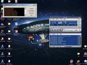
The design is also a useful embedded-systems example because it connects several technologies together: microcontroller firmware, infrared transmission, RS232 communication, and Windows control software.
Reusing an Old Remote Simplifies the Enclosure
The transmitter was installed inside an unused Hitachi VCR remote-control enclosure. Its original electronics were removed and replaced with a custom circuit containing the PIC16F627, 74LS32 OR gate, 2N3906 transistor, 78L05 regulator, 4MHz crystal, IR LED, and control buttons.
Reusing an existing remote housing provides ready-made button positions and a handheld enclosure without requiring a custom case. The main limitation is physical space, so PCB dimensions, button placement, battery arrangement, and internal wiring need to fit the original enclosure.
Infrared Transmission Carries Button Commands
When a button is pressed, the PIC16F627 assigns an ASCII value to that command and sends it through the communication routine. The transmitter uses the PIC's PWM hardware to create an approximately 38kHz carrier on the CCP1 output.
A carrier around this frequency is commonly used with infrared remote receiver modules because the receiver is designed to detect modulated IR rather than ordinary ambient infrared light. The IR LED and transistor driver stage then transmit the command toward the receiver.
PWM Hardware Generates the 38kHz Carrier
The firmware configures Timer2 and the CCP1 peripheral to generate the infrared carrier. PR2, CCPR1L, T2CON, and CCP1CON are configured so that the CCP1 pin produces an approximately 38kHz PWM signal.
Using the microcontroller's hardware PWM peripheral is preferable to manually toggling the output in software because the carrier timing can continue consistently while the processor handles button detection and command logic.
Buttons Are Mapped to Individual ASCII Commands
The program continuously monitors the connected buttons and assigns different ASCII characters to each detected input. Values beginning with ASCII 0 and continuing through later digits are transmitted according to the button pressed.
Some commands wait until the button is released before sending another value. Others, such as controls intended for continuous adjustment, introduce a short delay so the user can hold the button while repeatedly sending commands without changing the value too quickly.
This provides a simple command protocol because the receiver only needs to identify the incoming character and associate it with the corresponding Winamp action.
IR Receiver Converts Optical Signals Back to Data
On the computer side, an IRM8061 infrared receiver module detects the modulated infrared signal transmitted by the handheld controller.
The exact pin arrangement of IR receiver modules can differ between manufacturers and models, so VCC, GND, and signal connections should be confirmed from the component datasheet before applying power. Incorrect wiring can prevent operation or damage the receiver.
MAX232 Provides RS232 Level Conversion
The received command must ultimately reach the computer's serial port, but the voltage levels used by RS232 are different from the logic-level signals used by the receiver electronics.
A MAX232 interface IC performs this conversion, allowing the low-voltage digital circuit to communicate safely with the PC's RS232 interface. This is an important part of the design because connecting logic-level signals directly to a traditional serial port would not provide the required electrical compatibility.
Serial Communication Settings Must Match
The transmitter code initializes communication at 1200 baud with eight data bits, one stop bit, and no parity. The receiving software must use corresponding parameters so that transmitted command bytes are interpreted correctly.
If baud rate, data format, or other serial settings do not match, the computer may receive incorrect characters or fail to recognize commands entirely. Checking serial configuration is therefore one of the first troubleshooting steps when the IR link appears to work but Winamp does not respond correctly.
Visual Basic Converts Commands Into Winamp Actions
A Visual Basic application running on the computer receives the serial commands and translates them into keyboard actions associated with Winamp's global hotkeys.
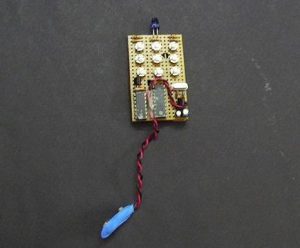
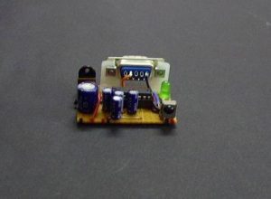
This separates the project into two logical layers. The PIC-based hardware handles physical button presses and IR communication, while the Windows application decides what each received command should do inside Winamp.
That arrangement also makes the hardware potentially reusable. By changing the PC-side software and command mappings, the same basic remote-control concept could be adapted to other desktop applications.
Winamp Global Hotkeys Must Be Enabled
The project depends on Winamp's global-hotkey feature. Global hotkeys allow predefined keyboard commands to control playback even when the Winamp window is not currently active.
The appropriate hotkeys therefore need to be enabled and configured before the Visual Basic program can reliably trigger actions such as playback control, volume changes, or track navigation.
Troubleshooting Should Start With Power and IR Hardware
If the remote works only at very short range, the first components to inspect are the IR LED, its polarity, the transistor drive stage, battery voltage, oscillator operation, and alignment between the transmitter and receiver.
The 78L05 output should also be checked to confirm that the logic circuitry receives a stable supply. A weak IR LED drive signal or incorrect carrier generation can significantly reduce communication range even when the firmware itself is functioning correctly.
A Useful Project for Learning Embedded Communication
This project demonstrates how a microcontroller can connect physical controls to desktop software through several communication stages. A button press is detected by the PIC16F627, encoded into data, transmitted through modulated infrared, received by an IR module, converted to RS232 levels, and interpreted by a Visual Basic application.
For learners, this makes the circuit useful for understanding GPIO input, PWM generation, IR communication, serial protocols, voltage-level conversion, and PC-to-microcontroller integration within one practical project.
Source: WINAMP IR CONTROL CIRCUIT VISUALBASIC PIC16F627 RS232
Quick Solutions to Questions related to WINAMP IR CONTROL CIRCUIT:
- What microcontroller is used in the circuit?
The circuit uses a PIC16F627 microcontroller. - Which IR receiver is used in the project?
The project uses an IRM8061 IR receiver. - How does the circuit interface with Winamp?
The circuit connects to Winamp via an RS232 interface. - What software sources are provided?
C source code for the PIC firmware and Visual Basic source code for the control software are provided. - How many control buttons does the design support?
The design is based on a 6-button control interface. - Is a MAX232 used in the design and why?
Yes, a MAX232 is used as a level shifter for the RS232 interface. - Can the Winamp control circuit be used in other projects?
Yes, the article states the control circuit can be useful in different projects outside Winamp.
Related projects
PIC microcontroller power supply circuit by Chayapol
This is 5V portable power supply circuit for pic microcontroller experiments. or PIC microcontroller power supply circuit. As The PIC16F627A microcontroller use...
LED Projects · PIC16F627A6 Digits LED 7-Segment Multiplexing using PIC16F627A
In the post 'LED 7-Segment Multiplexing', I have explained about the concept and benefits of multiplexing. Multiplexing implementation is very similar to...
LED Projects · PIC16F627ABinary/bcd to 7-segment decoder for PIC16F627A
Overview This is a building block project I developed to try out a few ideas. It decodes a 4-bit binary word to...
Communication & Interfacing · PIC18F4520CAN FD Node based on a PIC18 Microcontroller
The introduction sets the stage for an embedded systems project that involves developing a Embedded C CAN FD project using the MCP2517FD...
Communication & InterfacingLAN9662 Gigabit Switch: Optimized for Industrial Ethernet
Introduction It should come as little surprise therefore that one element of what is now more commonly referred to in some circles...
Communication & InterfacingPIC Microcontroller: Fundamentals & Applications for Students
Introduction Microcontrollers are the key components in the embedded systems market. A variety of embedded systems was formed and developed after the...

Muhammad Bilal
I am a highly skilled and motivated individual with a Master's degree in Computer Science. I have extensive experience in technical writing and a deep understanding of SEO practices.