Summary of Efficient Power Generation with Microcontroller-Controlled Thermoelectric Generators
The article describes design, testing, and performance analysis of a Microcontroller-Controlled Geothermal Thermoelectric Generator (MCGTG) that converts geothermal heat into electricity using 12 Melcor CP1.4-127-06L thermoelectric modules. A PIC16F877 microcontroller manages temperature, charging, and safety (UTL, solenoid valve, alarms) with an LCD interface. Experimental tests with hot water showed up to 28.12V open-circuit at ΔT=43°C and maximum power ≈6.15W (efficiency ≈2.5%). Improvements suggested include better cooling/heating surfaces, more or lower-resistance modules, and parallel units; system suits geothermal sites >70°C.
Parts used in the Microcontroller-Controlled Geothermal Thermoelectric Generator (MCGTG):
- Thermoelectric modules Melcor CP1.4-127-06L (12 units)
- Aluminum heating block
- Aluminum cooling block
- PIC16F877 microcontroller
- LM35 temperature sensors
- Liquid Crystal Module (Xiamen GDM2004D 4x20 LCD)
- Voltage dividing circuit
- Accumulator (battery)
- DC/AC converter and regulator circuit
- Solenoid valve (microcontroller-controlled)
- Alarm control circuit (voice warning at 4 Hz)
- Buttons for UTL adjustment (B1 and B2)
- KSYSTEM switch (accumulator charging circuit)
- R load resistors used in testing (10Ω, 30Ω, 50Ω and range 1Ω–80Ω)
- Diode D1 in accumulator charging circuit (threshold VD = 0.81V)
INTRODUCTION
The global demand for electrical energy continues to rise steadily, necessitating a shift towards renewable energy sources as traditional fossil fuels like petroleum and coal become increasingly scarce and contribute to environmental pollution. Consequently, there has been a surge in research focused on harnessing electrical energy from thermoelectric modules.
One such study delves into the development of a Microcontroller-Controlled Geothermal Thermoelectric Generator (MCGTG), aimed at directly converting geothermal energy – a renewable energy source – into electrical energy. The study involves the design, testing, and performance analysis of the MCGTG system, highlighting its potential in sustainable energy production [2].
MATERIAL AND METHOD
2.1. Thermoelectric Generator
The foundation of the thermoelectric generator (TEG) rests upon the Seebeck effect, originally discovered by Thomas Seebeck in 1821. Thermoelectric energy generation, a process wherein heat flow is directly converted into electrical energy, offers longevity and reliability due to its silent operation, simplicity, and lack of moving parts, requiring minimal maintenance. Thermoelectric modules consist of P and N type semiconductors connected electrically in series and thermally in parallel between two ceramic layers. In a TEG setup, one face of the thermoelectric module is heated while the other is cooled within the thermoelectric circuit, forming a load connection at the endpoints of the module. The schematic representation of a TEG is depicted in Figure 1 [3-7].
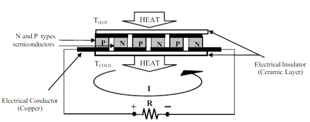
The thermoelectric generator (TEG) component within the designed system comprises three main parts: a heating block, a cooling block, and an arrangement of thermoelectric modules. In this setup, heat generated by the heating block is transferred to one side of the thermoelectric module, while the cooling block absorbs heat from the opposite side, facilitating the transfer of TEG heat. Aluminum blocks were utilized to heat and cool the surfaces of the thermoelectric modules. The system employed an arrangement of 12 thermoelectric modules (Melcor CP1.4-127-06L), electrically connected in series and thermally connected in parallel. This configuration effectively increased the output, thereby ensuring the accumulator charger’s power reached a sufficient level.
2.2. General Construction and Operation of System
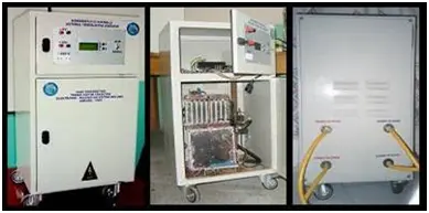
On the front panel of the Microcontroller-Controlled Thermoelectric Generator (MCGTG), there are outputs for 5V DC, 12V DC, and 220V AC generators, a Liquid Crystal Module (LCM) displaying system operation information and warnings, buttons for adjusting the upper temperature limit (UTL) value, and the on/off switch for the accumulator and TEG unit (refer to Figure 2). On the back panel of the MCGTG, there are inputs and outputs for geothermal water and cool water. The system specifications are detailed in Table 1.
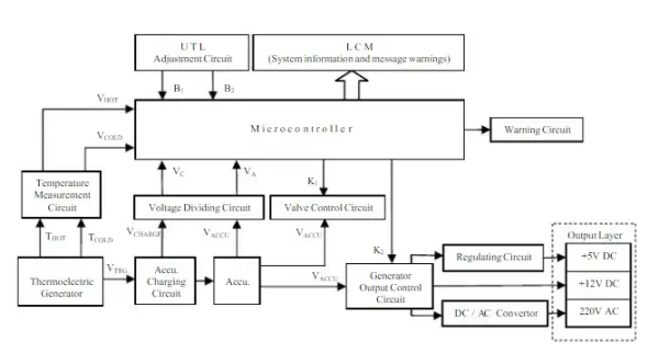
When supplying geothermal and cool water to the MCGTG system, a temperature difference between the faces of the thermoelectric module generates DC voltage. This DC voltage, assisted by the charging unit, charges the accumulator. The 5V DC, 12V DC, and 220V AC outputs are generated by the accumulator, DC/AC converter, and regulator circuit within the system. Activation of the thermoelectric generator and accumulator is initiated by the KSYSTEM switch within the accumulator charging circuit. Control signals, derived from temperature and voltage measurements, are managed by the microcontroller. VHOT and VCOLD voltage values, along with VA and VCanalog voltage values obtained from the voltage dividing circuit for VACCU and VCHARGE, are fed into the microcontroller’s analog inputs. Necessary adjustments are performed based on data and information regarding temperature differentials, UTL thresholds, accumulator and charging voltages, charging current, and operational details, all of which are displayed on the LCM. The block diagram of the MCGTG is illustrated in Figure 3.
Using temperature sensors within the temperature measurement circuit, the temperatures of the heating and cooling blocks are gauged, and analog voltages V_HOT and V_COLD are fed into the microcontroller. A linear approach is adopted in the temperature measurement circuit, employing LM35 temperature sensors which yield a 10mV output for each 1°C rise in temperature. Given that the PIC16F877 microcontroller operates with a reference voltage of 5V and features a 10-bit A/D converter, the sensitivity is estimated to be approximately 5mV, derived from 5/2^10.
This setup ensures that for every 5mV increment in the microcontroller’s analog input, measurements can be conducted with a sensitivity of 0.5°C. The analog voltages for accumulator charging (V_CHARGE) and the accumulator itself (V_ACCU) undergo division via a voltage dividing circuit, reaching levels of V_A and V_C, respectively, which remain below 5V, ensuring compatibility with the microcontroller.
Within the system, once the heating block temperature surpasses the Upper Temperature Limit (UTL), the supply of geothermal water is automatically halted. Likewise, should the accumulator voltage drop below 10V, the generator outputs are deactivated, accompanied by an audible warning alert. To facilitate this, an alarm control circuit capable of emitting a 4 Hz frequency voiced warning is utilized, connected to the RD1 port.
Given that the thermoelectric modules utilized in the design can withstand temperatures of up to 130°C, a Upper Temperature Limit (UTL) has been established, and precautions have been implemented to safeguard against extreme temperatures [8, 9]. The UTL value is continuously displayed on the Liquid Crystal Monitor (LCM), and a circuit has been devised to adjust this value incrementally by 1°C with each press of the B1 and B2 buttons. The signals for increasing and decreasing the UTL are routed to the RC5 and RC6 ports of the microcontroller. A microcontroller-managed solenoid valve is employed to automatically halt the flow of geothermal water input once the heating block temperature reaches the UTL, and it resumes flow when the temperature falls 5°C below the UTL. The RD4 port of the microcontroller is utilized to control the opening and closing of the solenoid valve.
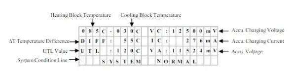
A Xiamen GDM2004D series 4×20 character LCD module was employed to display the results and system condition messages of the microcontroller-based system within its operational environment. The LCD screen layout is depicted in Figure 4.
2.3. Microcontroller and Software
The system’s control and analog-to-digital conversion tasks, as well as the organization of operational data, were managed by a PIC16F877 microcontroller from the MicroChip family [10]. The voltages VA and VC from the voltage dividing circuit, along with the VHOT and VCOLD values from the temperature measurement circuit, were directed to the microcontroller’s analog inputs (RA0, RA1, RA2, and RA3). These analog voltages were then converted into digital signals by the microcontroller’s internal A/D converter. Various ports of the microcontroller were utilized for specific functions within the system: RD4 for solenoid valve control, RC5 and RC6 for UTL adjustment, RC7 for managing 5V DC and 12V DC generator outputs, RD1 for voice warnings, and RB0-RB5 for the liquid crystal module (LCM).
Programming of the PIC16F877 microcontroller was accomplished using the Parsic program, which generated assembly codes based on digital logic principles. These assembly codes were then compiled into hexadecimal codes using the MPASM compiler.
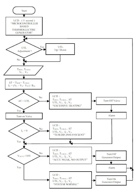
The microcontroller program operates in a loop, as depicted in the flow diagram, initiating with a 5-second opening message displayed on the LCM (Figure 5). Afterward, the microcontroller acquires VA, VC, THOT, and TCOLD values following the examination of B1 and B2 button inputs. Subsequently, it calculates the temperature difference (∆T) and the accumulator charging current (IC). The LCM displays THOT, TCOLD, VC, and VA values obtained from analog inputs, along with IC and ∆T values derived from calculations.
If the temperature difference (∆T) surpasses the UTL threshold, indicating extreme heating in the heating block, the microcontroller shuts off the geothermal water input valve and issues a written and voice warning. Additionally, as long as VC is less than the sum of VA and VD, indicating insufficient electrical energy from the TEG for accumulator charging, the microcontroller issues a warning regarding the inadequate temperature difference. Here, VD represents the threshold voltage of the D1 diode in the accumulator charging circuit, measured at 0.81V.
Furthermore, when there is no electrical energy production in the generator and the accumulator measurement voltage drops below 10V, the 5V DC and 12V DC outputs are disabled to prevent complete discharge of the accumulator, accompanied by a written and voice warning. These generator outputs are re-enabled when the accumulator voltage exceeds 10V after sufficient charging. Control of inputs is managed through the microcontroller’s RC7 port, facilitating toggling on and off as required.
3. PERFORMANCE ANALYSIS OF THE SYSTEM
3.1. Input-Output Parameters
Through a performance analysis of the thermoelectric generator, the operational parameters for achieving maximum power output from the system were identified. The system’s output power was evaluated by recording voltage and current values corresponding to the temperature differential across the thermoelectric generator. Graphs illustrating the relationship between load and power were generated based on these measurements.
Experimental measurements involved supplying hot water generated by a water heater to the geothermal water input of the MCGTG system, enabling measurements to be taken across a temperature range of 20°C to 70°C. By connecting a voltmeter across the terminals of the TEG thermoelectric module configuration, a DC voltage value of 28.12V was recorded at a temperature difference of 43°C.
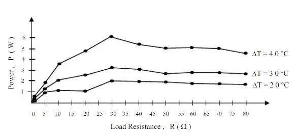
The system determined its output power by analyzing the current and voltage measurements obtained from R loads of 10Ω, 30Ω, and 50Ω connected to the terminals of the thermoelectric module arrangement. The relationship between system load and power was derived from current, voltage, and power values corresponding to fixed load resistances at various temperature differences. This load-power relationship is illustrated in Figure 6.
TEG Efficiency
The input power represents the cumulative heat energy introduced into the system, driving the production of electrical energy due to temperature differentials across the thermoelectric module. Conversely, the output power is determined by the voltage and current values extracted from the thermoelectric generator, a direct consequence of the temperature gradient. Consequently, the system’s input-output power and efficiency can be readily derived using TEG efficiency calculations (refer to the appendix) [2,8,9].
The CP1.4-127-06L model thermoelectric module employed in the TEG consists of a micromodule with 127 couples (N). The geometric factor of this thermoelectric module is measured at 0.118 cm. By measuring THOT=70°C (343.2 K) and TCOLD=27°C (300.2 K) within the system, material parameters such as α=0.000207V/K, ρ=0.00116Ω.cm, and κ=0.0153W/cm.K were derived from the thermoelectric module. Utilizing these values, the average Seebeck coefficient (αM) was determined as 0.0526V/K, the module’s average resistance (RM) as 2.4969Ω, and the module’s thermal conductivity (KM) as 0.4586W/K.
Within the TEG setup, 12 thermoelectric modules were electrically connected in series and thermally connected in parallel. Consequently, the series thermoelectric module count (NS) was 12, the parallel lines count (NP) was 1, and the total thermoelectric module count (NT) was 12. Optimal power output occurs when the load resistance (RL) matches the generator’s internal resistance. Accordingly, the load resistance was approximated to be 30Ω from 12 times RM. The current (I) drawn from RL was computed as 0.4526A, the output voltage of the TEG (Vo) as approximately 13.5792V, the generator output power (Po) as 6.1459W, the TEG’s total heat input (Qh) as approximately 253.5672W, and the TEG’s efficiency (η) as approximately 2.5%.
4. RESULT AND SUGGESTIONS
This study involved the design and testing of a microcontroller-controlled thermoelectric generator, which directly converts geothermal energy into electrical energy, a renewable energy source. The system’s control signals are managed using the PIC16F877 microcontroller. Geothermal water is utilized for heating the thermoelectric generator (TEG), while regular cold water from various sources is employed for cooling. The TEG consists of 12 CP1.4-127-06L model thermoelectric modules, designed with an adjustable surface temperature to accommodate the maximum working temperature of +130°C.
A specially designed heating block is utilized to apply thermal temperatures to the thermoelectric module. However, instead of geothermal water, solar-heated water or direct solar energy can be utilized for electrical energy production with minor modifications to the system. Experimental measurements were conducted using hot water from a water heater instead of geothermal water. The voltage produced by the TEG under a temperature difference of 43°C, while unloaded, measured 28.12V. Power outputs were determined by varying load resistances from 1Ω to 80Ω, with maximum power achieved using a 30Ω load resistance (1.96W at 20°C, 3.28W at 40°C, and 6.15W at 40°C).
Theoretical and experimental methods yielded similar results for TEG power, with an efficiency of approximately 2.5%. Efficiency remained consistent regardless of series or parallel thermoelectric module connections but could vary due to internal resistances of the modules. However, due to the use of high internal resistance thermoelectric modules for cooling, efficiency was relatively low. Strategies for enhancing output power include increasing cooling and heating surfaces, augmenting the number of thermoelectric modules, employing low internal resistance modules, and parallel connection of multiple units.
Considering the experimental results and electrical energy production, it is feasible to generate electricity in geothermal regions where temperatures exceed 70°C. This system holds significance in addressing the electrical energy needs of such regions endowed with thermal resources. Given the renewable nature of geothermal energy, the suitability of thermoelectric modules for low to middle temperature thermal regions, and the abundance of such geothermal resources, the utilization rate of this system is expected to be high. Its importance lies in providing a cost-effective, clean, and easily accessible solution to meet electrical energy demands.
- What is the main purpose of the MCGTG?
To directly convert geothermal energy into electrical energy using thermoelectric modules controlled by a microcontroller. - Which thermoelectric modules are used in the system?
Melcor CP1.4-127-06L thermoelectric modules, 12 units electrically in series and thermally in parallel. - What microcontroller is used to manage the system?
The PIC16F877 microcontroller is used for control, A/D conversion, and managing inputs/outputs. - How are temperatures measured in the system?
LM35 temperature sensors measure heating and cooling block temperatures, providing 10mV per 1°C output to the microcontroller. - What safety measure stops geothermal water flow at high temperature?
A microcontroller-controlled solenoid valve halts geothermal water when heating block temperature exceeds the Upper Temperature Limit (UTL). - What outputs does the MCGTG provide?
The system provides 5V DC, 12V DC, and 220V AC outputs generated from the accumulator, DC/AC converter, and regulator circuit. - What was the measured open-circuit voltage at ΔT = 43°C?
The unloaded DC voltage measured across the TEG configuration was 28.12V at a 43°C temperature difference. - What maximum power and efficiency were observed?
Maximum measured power was about 6.15W with an efficiency of approximately 2.5%. - How does the system prevent accumulator over-discharge?
If accumulator voltage drops below 10V, generator outputs are disabled and a written and voice warning is issued until voltage recovers above 10V. - What improvements are suggested to increase output power?
Increase cooling and heating surfaces, add more thermoelectric modules, use low internal resistance modules, and connect multiple units in parallel.