Summary of 0-9999 seconds count down timer using PIC12F683 microcontroller
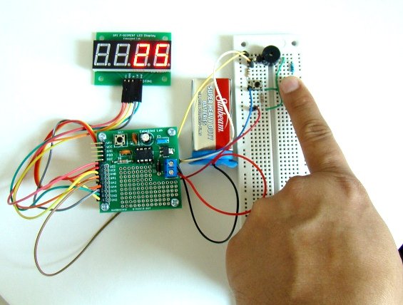
This project builds a simple 0–9999 second countdown timer with alarm and a 4-digit seven-segment display. Time is set via two tact switches read as different ADC voltages by a PIC12F683; display driving is handled by a MAX7219; a buzzer is driven by a 5 kHz PWM on GP2 for the timeout alarm. Firmware is written in C (mikroC Pro) and includes a MAX7219 driver adapted from a prior project.
Parts used in the 0-9999 seconds count down timer:
- PIC12F683 microcontroller
- MAX7219 display driver IC
- 4-digit seven-segment LED module (common cathode)
- Two tact switches (INC and TSET)
- Two 4.7K resistors (voltage divider for TSET)
- Pull-up resistor for ADC input (to 5V)
- Buzzer (piezo or similar)
- Supporting passive components (wiring, decoupling capacitor(s))
- Power supply (5V)
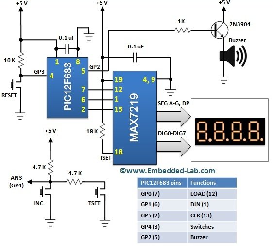
 Circuit diagram
The complete circuit diagram of this project is shown below. Two tact switches (named INC and TSET) are used for setting time and turning the timer on. These switches are connected in parallel and their inputs are read through the AN3 ADC channel of PIC12F683 microcontroller. You can see from the circuit diagram how these two tact switches give rise to different analog voltages when pressed. When INC is pressed, the input voltage to AN3 pin is 0. But if TSET is pressed, the input to AN3 ADC channel would be around 2.5V (two 4.7K resistors make a voltage divider network). And if none of them are pressed the ADC input is pulled up close to 5V. Therefore, based on the value of 10-bit ADC count, it is possible to detect and identify if any of the two switches is pressed. The buzzer is driven by a PWM signal generated at the GP2 output pin of PIC12F683. The display part uses a 4-digit seven segment (common cathode type) LED module which is driven by the MAX7219 IC. If you are not familiar with MAX7219 device, please read my earlier project Serial four digit 7-segment LED display module for further detail on that.
Software
The firmware is developed in C and compiled with mikroC Pro for PIC compiler. The driver routine for MAX7219 is taken from my previous project Serial four digit 7-segment LED display module. A 5KHz PWM signal is generated at the CCP1 output pin for the audible alarm when the timer is out. The overall operation of this timer project is described in the next section. That will help you to understand how the firmware for this project works. Here’s the complete source code for this project.
For more detail: 0-9999 seconds count down timer using PIC12F683 microcontroller
- How is time set on the timer?
Time is set using two tact switches named INC and TSET, whose presses are detected via different ADC voltages on the AN3 input. - Can two switches be read using one ADC pin?
Yes; the two switches produce distinct analog voltages via a resistor network so the PIC12F683 AN3 ADC can distinguish them. - What drives the seven-segment display?
The MAX7219 IC drives the 4-digit seven-segment LED module. - Which microcontroller handles I/O and timing?
The PIC12F683 microcontroller handles all I/O and timing operations. - How is the alarm generated when time runs out?
An audible alarm is generated by driving a buzzer with a 5 kHz PWM signal from the PIC12F683 CCP1/GP2 output. - What compiler and language are used for firmware?
The firmware is written in C and compiled with mikroC Pro for PIC. - Is there an existing MAX7219 driver used?
Yes; the driver routine for MAX7219 is taken from an earlier Serial four digit 7-segment LED display module project. - What ADC behavior indicates each switch state?
INC pressed yields about 0V at AN3, TSET pressed yields about 2.5V via two 4.7K resistors, and none pressed pulls AN3 near 5V.