Background
From the first robot I ever made, I have always felt that when designing the motors, wheels and drive train, it will almost always be important to know where you are – that is, to have some sort of encoder feedback. So the first robot I built used stepper motors, but I found that they were difficult to deal with because of the complex drive circuit required, and they are usually under-powered. It’s also difficult to get a smooth speed ramp with them, and if they ‘skip’, that is, you send them five pulses and they only move three or four because of over-torque, an obstacle, etc, then you will never know it. Not to mention the processing overhead required to generate two pulse-trains with different frequencies (one for each wheel). The next logical step is to go with a servo motor (the word servo designates any motor that has a position-feedback mechanism. For this article, I will be referring to a standard brush DC motor with encoder feedback, rather than the hobby R/C servos with potentiometer feedback). Having closed-loop control of a motor with true encoder feedback allows a much higher degree of accuracy when controlling and reading the position of your motor. The challenges involved with this method are:
- Adding an encoder to your motor or wheel
- Allocating the processing power to keep track of all these pulses and actively control the motor.
- Designing or finding the power side of the motor driver circuit, such as an H-bridge
Recently it seems like it is getting easier to find fairly good motors with built-in encoders, or encoders that can easily be attached to a drive shaft or wheel, that make the first item easier than it has been in the past. Several people have published quadrature black/white printable patterns to stick on to wheel, to provide encoder feedback. Check out the excellent SRS Encoder article by David Anderson, http://www.seattlerobotics.org/encoder/200109/dpa.html. This article has the postscript code to make encoders as well. As for the second and third items, allocating a chip or board just for controlling your motor, there are several options:
- Buy an LM629 precision motor control chip for $30. This chip does full PID control of position, velocity and acceleration. Requires ~15 lines of I/O to talk to it, and takes about 75-100mA of current just to run this chip. Need to design your own board to mate it to an H-Bridge circuit and a master processor such as a PIC or large Stamp.
- Buy a Motor Mind II, for $30. This is a speed controller and H-bridge combined, which is a good value. Great for controlling velocity of motors up to 2 Amps, but since it only has a tachometer input, rather than full quadrature encoder input, you never really know which direction the motor is going, just the speed of the pulses. This means that for accurately tracking position, and for “locking on” to a certain position or coordinate, the Motor Mind is not the best choice.
- Make a home-brew PID controller and H-bridge combination board
As you may have guessed, I opted for number 3: Make my own. Actually my first choice, as mentioned above, was to go with stepper motors. Then I went with two LM629s paired with LMD18200 3A H-bridges. Because of the 8-bit data bus on the LM629, I needed a lot of I/O lines to talk to it, so I used a 40-pin PIC. Those five chips alone cost me over $95, and I hadn’t even made a board yet! I ended up assembling the parts on a PIC proto board I got free from Microchip when I attended a seminar. It was point-to-point soldered and ugly, but the thrill I got when it was finally working has really stuck in my mind, and motivated me to make this solution cheaper and simpler by doing some development of my own. Since PICs are cheap, I thought if I spent enough time and research, I could program a PIC to do almost everything that LM629 does. I also figured that since I’m going to invest the time and money to research the PID algorithms and make a custom board, that I may as well make it as flexible and useable as possible, so others can use it in their designs.
Overview
The base processor is a PIC16F876, which is a 28-pin PIC processor, running at 20MHz. It is paired with an LMD18200 H-bridge, which can drive 3A continuous loads, 5A peak. I have set the base requirements for the software and hardware as follows (many of these requirements came from the goal of emulating the capabilities of the LM629 chip):
- 32-bit registers to hold fixed point position variables (up to +/8 million encoder counts)
- Optional “tachometer” mode, which allows using the circuit with single encoders, rather than full quadrature encoders. For many applications, speed control is enough, and it greatly simplifies finding/making quad encoders
- 16-bit factors to hold Kp, Ki, and Kd constants
- 10-bit PWM resolution for motor output power/speed control
- High speed encoder capture logic (up to 254,000 counts/sec, or encoder pulses as fast as 2us wide). For an encoder with 1200 counts/revolution, speeds up to 12,700 rpm are possible
- True real-time PID control with adjustable filter constants
- Trapezoidal Trajectory Profile processing (constant accel ramp, constant velocity cruise, then constant decel rampdown)
- Storage of up to 24 trajectory profiles in flash EEPROM
- Fast PID recalculation, updating approx every 510 usec.
By starting with these requirements, I began formulating the skeleton of the software algorithms and hardware requirements, which eventually led to the selection of the particular processor to use, and the software feature set that I could support. I have designed the prototype PC board, and while waiting for it to arrive, I have successfully made a breadboard version of the circuit, as a platform for software development.
Technical Details
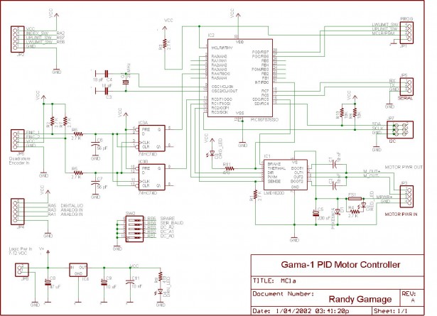
To capture the rapid quadrature encoder counts, I used the Timer/Counter inputs on the PIC. Unfortunately these inputs only count in the Up direction, so I used a D Flip-Flop to decode the encoder pulses into two streams: one for up-direction counts, and one for down-direction counts. Then every update cycle I simply subtract the down counts from the up counts, and get the net distance change. This distance change becomes the actual velocity, since it is a distance change in a fixed period of time. It is added to the current 32-bit position register. The error term is calculated by subtracting the current position from the target position. Here’s the current version of the schematic diagram (this is not finalized):
 The Proportional filter term acts on the error term, basically Yp = Kp x Error. The Differential term acts on the Velocity term, and becomes Yd = Kd x Velocity. The integral term is calculated in two parts. First, a running total is updated, which is just a constant error accumulator: Integral = Integral + Error. Then the filter term is calculated: Yi = Ki x Integral. The final result, Y = Yp + Yi + Yd, is used to set the output power, which is a PWM duty cycle.
I decided to use locked anti-phase PWM, in which a 50% duty cycle conveys zero power, 100% is full power, and 0% duty cycle is Full Reverse. I am using this because after reading many discussions and articles on the subject, it seems like it allows the H-bridge/Motor circuit to run more efficiently, and it reduces roll after stopping. However, I designed the board so that by simply changing the firmware, I could also use signed PWM, in which one pin is used for direction control, and one pin for speed.
Interface Options
In keeping with my mission to make this board as flexible as possible, I have ambitiously attempted to support three different communication modes: Serial, I2C, and Cricket Bus.
The serial mode is at 19,200 baud, and uses standard text commands, to allow running the board from a terminal program like HyperTerminal. There is no MAX232 on board for level-shifting, so the user will have to provide an adapter. I am assuming most people will interface this board to another microcontroller, and usee the PC only for tuning/debugging.
The I2C mode will be a register setting type of protocol, where you read and write data to registers in order to set the Kp, Ki, Kd, etc. and for sending commands. I haven’t begun implementing this code yet.
The latest change I have made to the design is to add a Cricket bus connector, to allow one-wire communications with the new Handy Cricket devices. These are small, powerful robot controllers designed by Fred Martin of Handyboard fame. If you are interested, check them out at http://handyboard.com/crickets. They are not nearly as powerful as the Handyboards, but for students and anyone just getting into robotics, they have an interesting set of features.
Current Project Status
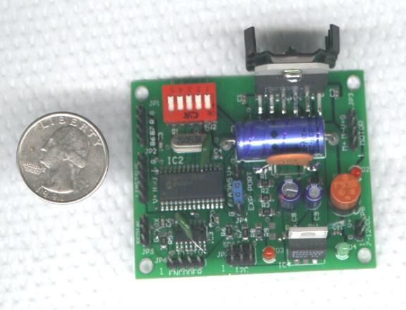
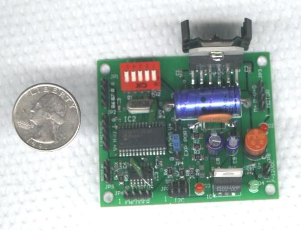
Here is a picture of the first PC Board prototype:

You’ll see some jumpers and add-ons- I’ve learned a lot lessons by making this prototype, and I’m in the process of getting the rev 2 board finalized.
I have successfully programmed and tested the core PID loop that reads and tracks the encoders, performs the interrupt timing and velocity calculations, and the 32-bit multiplication routines for the three factors of the PID filter logic. The P portion, the proportional term, is now working very well. The I portion, the integral term, is a little more tricky. I have found that the general formulas in the continuous domain are freely available, but when converting to the discrete domain, that is, dealing with quantized ‘chunks’ of time, people have been less forthcoming with their algorithms. I think it’s because when someone finally struggles through all of the complications of making a digital version of a PID controller, they want to protect it as a hard-won secret. I hope to share as much of my findings as possible with everyone in this area.
Some examples of the challenges are: when integrating the error term, you have to impose a max limit on the accumulated term, to avoid what’s called Integral Windup, where the I term gets so big that it causes a step-function power output to the motor. I have also found some ways to proportionally limit the integral accumulation, based on current velocity. This algorithm also prevents integral windup. Finally, I have spent quite a bit of time making sure that the scan rate, or main PID calculation loop, is adjustable to account for a wide variety of encoder densities (some motors have 2000 counts/rev, some homebrew ones only have as little as 8 or 10).
Some of the convenience features I have tried to incorporate into the board and software are as follows:
- Easily removable fuse for the motor power, with an LED indicator when it blows (not because I’ve ever shorted the motor power on a robot, no, not me 😉
- 4-position dipswitch to allow setting of baud rate, I2C address, etc.
- Encoder connector with power and ground pins, and on-board pullup resistors and signal conditioning.
- Expansion connector with three general purpose analog or digital I/O lines
- Three extra inputs dedicated to home switch, upper limit and lower limit switches, for applications where homing and indexing is important (CNC mill, etc)
- On-board flash memory to permanently store things like the PID constants, configuration, and motion trajectories.
- Two I2C connectors in parallel for easy daisy-chaining
- Separate motor power and logic power, for clean logic signals
- LEDs for Overtemp of H-bridge, fuse failure, and power indication
- Analog reading of motor current available via software commands. Allows control of motor torque, sensing of obstacles / force feedback, etc.
- Programming port connector, for easy firmware updates. I am considering eliminating this, however, just because I have been having great luck using a serial bootloader, and there’s already a serial port on the board. I am using MELoader from MELabs (www.melabs.com)
I am hoping that when all is said and done, I will have a nicely packaged board, about 2″ x 2.5″, including the smarts and the H-bridge driver, that only requires a two I/O lines to interface to (selectable Serial or I2C), that other hobbyists can incorporate into their robots.
Future Challenges
One of the things in the back of my mind for the future is to add a navigational processor onto the board, or connect it externally. The purpose would be to track wheel odometry data and do the dead-reckoning calculations to track current robot position and orientation. It seems like this would be great for contests like the firefighting and others where accurate dead-reckoning is an advantage. The frequent update-cycle would lead to more accurate calculations than most other robots that are too busy with other algorithms to calculate frequent dead-reckoning updates.
I welcome any interest and feedback (randy @ gamatronix.com) – I’m still in the development phase, so now’s the time to make changes!
For more information about the board, please visit our web-site at: http://gamatronix.com
Randy Gamage

