
Summary of Binary/bcd to 7-segment decoder for PIC16F627A
This project is a microcontroller-based building block that decodes 4-bit binary or BCD inputs to drive 7-segment LED displays. Unlike standard ICs, it offers customizable segment data and an invert control for common anode or cathode modules. Implemented on a PIC16F627A/628A, it features lamp testing, zero blanking, and input latching with minimal external components.
Parts used in the Binary to 7-segment decoder:
- PIC16F627A microcontroller
- PIC16F628A microcontroller
- 100nF ceramic decoupling capacitor
- 4K7 pull-up resistors
- Current limit resistors
- 7-segment LED display
Overview
This is a building block project I developed to try out a few ideas. It decodes a 4-bit binary word to outputs that will drive a 7-segment LED display. Functionality is similar to the 7447 BCD-to-seven-segment decoder/driver IC however, because it’s implemented using a microcontroller, the segment control data can be customised to display any set of 16 characters you wish to create. It also has an ‘invert’ control input that allows it to drive either common anode (active low) or common cathode (active high) LED modules.
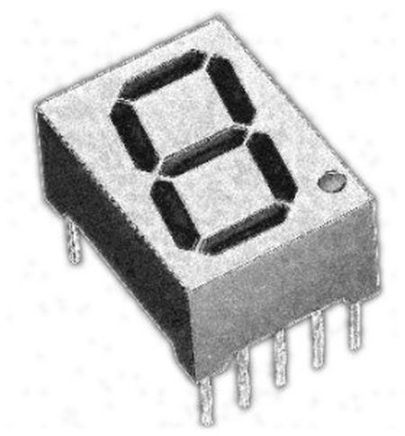
Binary or BCD to 7-segment decoder
- 4-bit binary input to 7-segment decode, 0-9, A-F
- Lamp test input
- Zero blanking
- output invert, allows use of common anode or common cathode displays
- input latch
- Outputs rated at 20mA per segment (Max)

The idea behind this project is that the PIC can be used as a decoder for 7-segment LED displays and therefore it will be built into some other application. The schematic is provided for evaluation only.
Operation
The PIC use an internal clock source so no external timing components are required, you will need to fit a decoupling capacitor across the Vdd/Vss supply close to the PIC; 100nF ceramic will do the job..
Inputs require an external pull-up resistor unless actively driven by an external source. All unused inputs should be tied to Vdd via a 4K7 resistors.
Because the decoder is implemented in software running on the PIC, input to output propagation delays are 15uS. Input data on A0-A3 should be held for 15uS after en/latch input goes high to ensure input is latched.
Outputs on the PIC16F627A / 628A are rated at 25mA with a maximum of 200mA for all I/O pins. This means it can drive a 7-segment LED display directly (via current limit resistors).
Customizing Segment Data
The segment data used to drive the outputs is held in the EEPROM of the PIC making it easy to edit without having to reassemble the source code.
The data is held at addresses 00 to 0F in the format shown below
For more detail: Binary/bcd to 7-segment decoder for PIC16F627A
- Can this project drive both common anode and common cathode displays?
Yes, it has an invert control input that allows driving either type. - Does the design require external timing components?
No, the PIC uses an internal clock source so no external timing components are needed. - What is the maximum current rating per segment output?
The outputs are rated at 20mA per segment with a maximum of 25mA. - How can I customize the characters displayed on the segments?
Segment data is stored in EEPROM addresses 00 to 0F, allowing easy editing without reassembling code. - What happens if unused inputs are left floating?
All unused inputs must be tied to Vdd via 4K7 resistors. - Is there a specific delay required for input data latching?
Input data should be held for 15uS after the en/latch input goes high to ensure proper latching.
