
Summary of PIC Microcontroller Based Electronic Lock
This article describes a PIC16F877A microcontroller–based electronic door lock that uses a 4x3 keypad and 16x2 LCD. A default password (*2345#) unlocks the door and can be changed by entering the master-change sequence (*23455#new 4 digit code). Passwords are stored in EEPROM; successful entry energizes a relay (simulated on PORTA bit 0/LED). The project is modular and demonstrates keypad input, LCD output, EEPROM storage, and relay control for access control.
Parts used in the Electronic Code Lock:
- PIC16F877A microcontroller
- 4x3 matrix keypad
- 16x2 LCD
- EEPROM (internal to PIC16F877A)
- Relay (lock actuator)
- LED (used for simulation on PORTA bit 0)
- Power supply
- Connecting wires and supporting passive components (resistors, capacitors)
Security is a prime concern in our day-today life. Everyone wants to be as much secure as possible. An access control for doors forms a vital link in a security chain. The microcontroller based digital lock for Doors is an access control system that allows only authorized persons to access a restricted area.
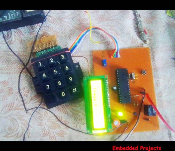 An electronic lock or digital lock is a device which has an electronic control assembly attached to it. They are provided with an access control system. This system allows the user to unlock the device with a password. The password is entered by making use of a keypad.
The user can also set his password to ensure better protection. The major components include a Keypad, LCD and the controller PIC16F877A. This article describes the making of an electronic code lock using the 16F877A microcontroller.
The system is fully controlled by the 8 bit microcontroller 16F877A which has a 8Kbytes of ROM for the program memory. The password is stored in the EPROM so that we can change it at any time. The system has a Keypad by which the password can be entered through it. When the entered password equals with the password stored in the memory then the relay gets on and so that the door is opened.
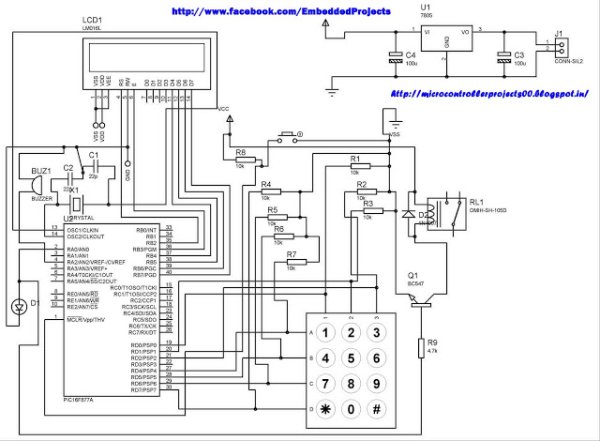
The code is built in a modular style to allow a user to find ways to modify project. In start the D Lock programs loads with a default code of “2345” format is *2345# which can be enter to unlock the door, the code cam be change by entering the master code in the format *23455#new 4 digit code. In this program i only display the result on LCD and lock will be placed at PORTA bit 0 where i put led for simulation.
A 4×3 matrix keypad and a 16×2 LCD have been used here. Keypad and LCD are very commonly used input & output devices, respectively. The password is stored in the system EEPROM.
For more detail: PIC Microcontroller Based Electronic Lock
- What microcontroller is used in the project?
The PIC16F877A microcontroller is used. - How is the password entered?
The password is entered using a 4x3 matrix keypad in the format *2345# for the default code. - Can the password be changed and how?
Yes, the code can be changed by entering the master change sequence *23455# followed by the new 4 digit code. - Where is the password stored?
The password is stored in the EEPROM of the PIC16F877A. - How does the system indicate a successful unlock?
When the entered password matches the stored password the relay gets on and the door is opened; in the project the lock is simulated with an LED on PORTA bit 0. - What output device displays status and messages?
A 16x2 LCD is used to display results and status. - Is the code modular and can it be modified?
Yes, the code is built in a modular style to allow users to modify the project. - What default code does the program load at start?
The program loads a default code of 2345, entered as *2345# to unlock.
