Summary of Servo Motor Controller using PIC12F629
This project uses a PIC microcontroller and a joystick plus a potentiometer to control two servos with bidirectional motion and variable speed. The micro measures resistance via RC charge timing to decode joystick positions, outputs 1 ms or 2 ms control pulses to drive servos clockwise or anticlockwise, and varies pulse repetition interval based on the pot to change speed. LEDs show pulse activity for testing. The design is suited for pan-and-tilt camera control, crane or model animations, and servo testing.
Parts used in the Servo Motor Controller:
- PIC microcontroller (PIC12F629 or similar)
- Joystick module (with multiple switch contacts)
- Potentiometer (variable resistor for speed control)
- Two servo motors (with red, black, white leads)
- Capacitor for RC timing
- Resistors (22k, 47k and others for RC network)
- Two LEDs (for pulse indication)
- Prototype board (or PCB)
- Battery or DC supply (positive and negative rails)
- Wiring and connectors
This project controls two servo motors – both clockwise and anticlockwise and has variable speed.
You can use the Joy Stick to “pan and tilt” a remote camera or provide “left-right-up-down” action for a crane or an animation on your model layout. The project also tests servo motors.
The CIRCUIT
The circuit is fairly simple.
The input from the Joy Stick has been separated into two sections to make detection easy and this requires 2 inputs.
A pot is connected to another input line and 2 more lines are required for the servos. Pin 8 is connected to 0v and pin 1 is connected to the supply. The only unused pin is GP3 (Input ONLY),
Most of the work is done by the micro. It uses a technique of charging a capacitor via a resistor and determining how long it takes to charge, to work out which switch is pressed or the position of the pot.
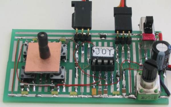
It then outputs a 1mS or 2mS pulse to one of the servo motors to create clockwise or anticlockwise rotation of the output shaft and the speed of rotation can be set by adjusting the pot. The two LEDs on the output pins let you see the pulses being delivered to the servo’s when the project is used to test these devices. The photo’s below show the circuit built on prototype board:
THE JOY STICK
There are 7 different (actually more) combinations of positions for the joy stick and we need to decode them and work out what to do with the result.
This is too many resistance-values for a single input and so we have used two inputs with 3 resistance-values for each plus the possibility of all switches being pushed at the same time.
The resistance values we have used are 22k and 47k. When 2 switches are pressed, the resistors are in parallel to produce 15k, but only 22k and 47k is detected in this program.
The program creates a loop that detects up to 19k, to produce an output of loop=1, then up to 38k for a value of loop=2 and higher than 38k for a value of loop=3. But if the program keeps looping for 10 loops, it determines that no button is pressed and creates a value of 4. The change-points are mid-way between the resistance-values we have used and thus any tolerances on the capacitors and resistors can be accommodated.
This means a resistance of 15k produces a value of 1, 22k produces a value of 2 and 47k produces a value of 3. This is most important as we don’t want the cut-off points to be on the border as the program may produce an output of 1 instead of 2. The project is fairly voltage sensitive and if the right-hand buttons are not detected, the battery voltage is low.
THE SERVO
A servo module consists of a motor and gearbox, with a PC board containing the electronics to drive the motor in clockwise and anticlockwise direction. The electronics also detects the width of the incoming pulse to drive the motor to mid-position and also other positions, but this feature is not used in this project.
The motor is connected to the positive rail of the supply via a bridge of transistors within the servo and the red and black wires from the module are taken to the positive and negative of a battery to provide the current to drive the motor.
The third lead (white) is the control line and this is taken to the micro.
This line needs a pulse and the maximum repetition-rate accepted by the servo is every 18mS – it will accept a longer timing between pulses. This is the timing between pulses, the actual pulse-width is very short, between 0.9mS and 2.2mS.
If the pulse is less than 1mS duration (wide) the servo will travel fully in the anticlockwise direction.
If the pulse is 2mS, the servo will travel in the clockwise direction.
If the pulse is 1.5mS, the servo will travel to the mid position.
If the time between pulses is longer than 18mS, the speed of rotation is decreased.
This is what we have done. We have provided a 1mS or 2mS pulse and created a long time-interval between pulses to produce a reduced rate of movement.
The program looks at the position of the pot and adds a number of milliseconds between each pulse to produce these long time-intervals.
As the resistance of the pot is increased, the pulses are less frequent and the speed decreases.
For more detail: Servo Motor Controller using PIC12F629
- How does the micro detect joystick position?
The micro charges a capacitor via resistors and times how long it takes to charge to determine resistance values corresponding to joystick switches. - Can one input decode multiple joystick switches?
No, the design uses two inputs to separate the joystick into sections so multiple positions can be distinguished. - What pulse widths drive clockwise and anticlockwise servo motion?
A 1 ms pulse drives the servo fully anticlockwise and a 2 ms pulse drives it clockwise; 1.5 ms gives mid-position. - How is variable speed achieved?
The program increases the time between pulses based on the potentiometer resistance, reducing the pulse repetition rate to slow the servo. - Why are 22k and 47k resistors used for the joystick?
They provide distinct resistance levels that the program decodes (22k => value 2, 47k => value 3) while parallel combinations give other levels. - What indicates the servo control pulses during testing?
Two LEDs on the output pins show the pulses being delivered to the servos for testing purposes. - Does the servo need a separate power connection?
Yes, the servo red and black leads are connected to the battery positive and negative to supply motor current; the white lead is the control signal from the micro. - What happens if the time between pulses exceeds 18 ms?
The servo will accept a longer interval and its speed of rotation is decreased, which the project uses to vary speed.