Summary of Prototyping with Microcontrollers, Sensors, and Materials
Prototyping a thermal insulation device: build a container to minimize heat loss from heated wax, measure temperature with a TMP36 sensor, and control it via an Arduino microcontroller. Lab covers basic electricity, components (breadboard, resistors, LEDs, push-button, diodes), Arduino hardware and programming (IDE, pins, sketches, functions), heat transfer principles, and a competition to optimize insulating capacity versus cost.
Parts used in the Thermal Insulation Device Prototype:
- Arduino UNO microcontroller / RedBoard
- USB cable
- Computer with Arduino IDE
- Breadboard
- Jumper wires
- Resistors (220 Ω, 2.2 kΩ, 10 kΩ)
- LED
- Push-button
- TMP36 temperature sensor (thermistor referenced)
- Insulating device materials (various, per Table 4)
Prototyping
Prototyping involves the creation of an initial model of a product to conduct testing. Whether the product is intended for consumers, government entities, or businesses, it typically starts as a prototype, which may not include all the components or functionalities present in the final market-ready version. Prototypes act as proof of concept, demonstrating that the system or device can be constructed and function effectively.
In this laboratory session, we will construct a prototype of a thermal insulation device. The primary purpose of this device is to minimize the rate of heat loss from a container of heated wax placed within it. To achieve this, the prototype will integrate a TMP 36 sensor, responsible for measuring heat loss, and will be controlled by a microcontroller.
Electricity
Electricity is the movement of electrons within a conductive wire. When there exists a disparity in charge between two points in the wire, electrons flow, creating an electrical current, which is quantified in amperes (A). Interestingly, the direction of electrical current is opposite to that of the electron flow. The disparity in charge that drives this electron movement is known as electrical voltage, measured in volts (V). Moreover, certain materials impede the flow of electrons, exhibiting electrical resistance, which is measured in ohms (Ω).
Ohm’s Law (1) articulates the relationship between the voltage across a resistor, the current (I) flowing through the resistor, and the resistance (R) of the resistor.
Fluctuations in voltage and current play a crucial role in digital signal processing, enabling the functioning of intricate systems and devices, as well as simpler ones like microcontrollers and household digital instruments.
Electrical Components
Several basic electrical components are used to build simple circuits.
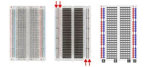
Breadboards
Breadboards, as depicted in Figure 1, are compact boards frequently employed for circuit prototyping. They offer a means to connect circuit components without making permanent connections. The red and blue strips situated on the sides of the board (referred to as power rails in sections A and D) are interconnected throughout the board, typically serving as power supply and grounding points. The rows between the power and ground strips (found in sections B and C) are also interconnected, usually utilized for linking various components. However, it’s important to note that sections B and C are not connected to each other across the central bridge of the board.
DC (Direct Current) Voltage Sources
DC voltage sources are commonly employed to energize circuits due to the presence of a voltage difference across their terminals. These sources typically comprise batteries, such as AA or AAA batteries. Arduino boards offer versatile power options, enabling them to be powered by a battery, a USB cable, or an AC adapter. Once the Arduino is powered, it can function as a 5V DC voltage source, making it suitable for various applications.
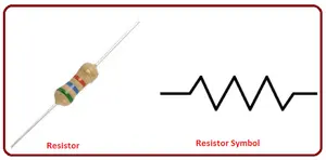
Resistors
Resistors, as shown in Figure 2, are electronic components designed to diminish the current passing through a circuit while converting the surplus current into thermal energy. They are among the most frequently used components in electrical circuits. The primary function of resistors is to control or limit the current flowing through other components. For instance, when connecting an LED to a battery, a resistor is employed to regulate the circuit and safeguard the LED from damage by restricting the current flow.
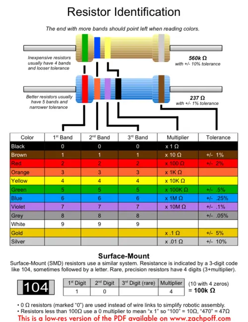
Resistors are color-coded in Figure 3 to signify their resistance value in ohms. Unlike polarized components, resistors are non-polarized, which means their orientation does not impact the circuit’s functioning.
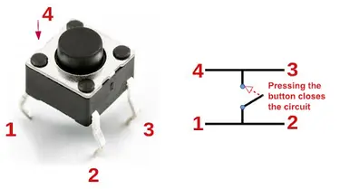
Push-Buttons and Switches
Push buttons and switches, as depicted in Figure 4, are mechanical devices used to interrupt or redirect current flow in a circuit. Basic push buttons are polarized, meaning they have a specific orientation that must be followed for proper operation. On the other hand, basic switches are non-polarized and can be used in either orientation without affecting their functionality.
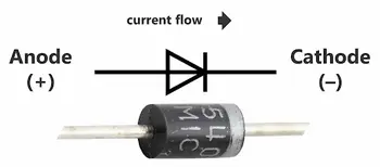
Diodes
Diodes are electronic components that permit current to flow in only one direction. In a diode, the anode serves as the positive terminal, while the cathode serves as the negative terminal. Additionally, diodes can function as signal amplifiers (Figure 5).
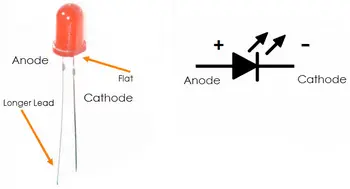
A light-emitting diode (LED) is a compact electric light that operates with low voltage and current (Figure 6). When dealing with LEDs, it is vital to note their polarity: the longer lead serves as the anode, while the shorter lead is the cathode. Proper orientation is crucial since LEDs are polarized components. Moreover, to prevent rapid burnout due to excessive current, most LEDs necessitate the use of a resistor in the circuit.
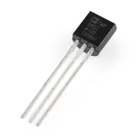
A TMP36 sensor (Figure 7) utilizes the voltage-temperature relationship inherent in diodes to effectively measure temperature. As the temperature changes, the voltage across the sensor’s diode also varies proportionally. By converting the output voltage, the sensor can provide an accurate temperature reading.
Microcontrollers
A microcontroller is an affordable, programmable computer that operates independently without peripherals like a mouse, keyboard, or screen. Microcontroller boards offer direct access to the input and output pins of their processing chips, enabling users to directly interact with sensors and execute actions. These microcontrollers serve specific functions in various applications, including household appliances, medical devices, automobiles, and other systems.
Arduino boards (Figure 8), which utilize microcontrollers, were designed for easy programming and integration into larger projects. Available in various shapes and sizes, some Arduino boards come with additional features like WiFi or Bluetooth connectivity. Different boards can also offer distinct capabilities, such as higher processing speeds and increased memory capacity.
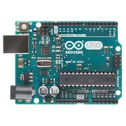
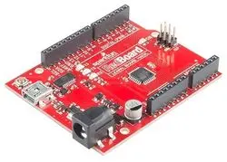
This lab will use an Arduino UNO board created by SparkFun called a RedBoard (Figure 9).
Arduino Hardware
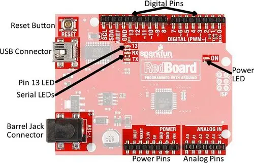
All Arduino boards feature a common layout resembling the one depicted in Figure 10. However, not all sections and pins will be utilized in this particular lab or for the Semester Long Design Projects.
– Reset Button: This button is used to restart the board.
– USB Connector: It provides power to the board and facilitates its connection to the computer.
– Pin 13 LED: This LED can be used directly without the need for an external LED circuit.
– Serial LEDs: These LEDs indicate whether the Arduino is transmitting or receiving data from pins 0, 1, or through the USB connection.
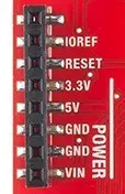
The power pins play a vital role in providing voltage to other pins and serving as ground connections (Figure 11).
– 3.3V: Typically utilized to power low-voltage sensors.
– 5V: Used for powering various circuits.
– GND: Represents the ground pin, with a voltage of 0V.
– VIN: Voltage-in pin, which can be utilized to power the board using an external voltage source or a battery.
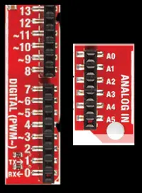
The digital and analog pins serve as means for conveying input and output commands to the microcontroller and electrical components (Figure 12). They are versatile, as they can be utilized with both analog and digital devices due to the Arduino board’s ability to convert analog inputs into digital inputs.
– A0-A5: These analog pins are uniform and enable the reading of data from sensors or the control of analog devices. They are capable of reading and writing values within the range of 0 to 1023.
– Digital Pins 0-1: Reserved as transmitter and receiver pins, and they are not used in this specific lab.
– Digital Pins 2-12: These digital pins can toggle between HIGH and LOW states, allowing for the reading and writing of values that are either HIGH or LOW. In contrast, analog pins provide a broader range of values.
– Digital Pin 13: This pin is connected to the onboard LED and should solely be employed as an input pin for this purpose.
The Arduino IDE (Integrated Development Environment)
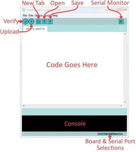
The Arduino IDE is a software application that allows users to edit, compile, and upload code to a compatible microcontroller. Figure 13 displays a screenshot of the program’s user interface.
– Verify: This function checks the code for errors and identifies any issues that need to be addressed.
– Upload: After verifying the code, this option performs the actual process of uploading the code to the Arduino board.
– Console: The console section displays any errors or issues detected in the hardware.
– Serial Monitor: This feature enables users to send and receive messages to and from the Arduino board, facilitating communication and debugging tasks.
Arduino Programming
The Arduino programming language draws its foundation from C/C++, but it is intentionally crafted to be more straightforward and user-friendly. The programming concept can be likened to constructing with LEGO blocks, adhering to specific rules while employing different building blocks to assemble more substantial components.
In Arduino programming, each line of code must conclude with a semicolon (;), except in the case of conditionals, loops, or functions. For annotations within the code, comments are initiated using two backslashes (//). These comments are text that the program disregards, serving as labels and explanations to clarify the code’s purpose and functionality.
Arduino Programs
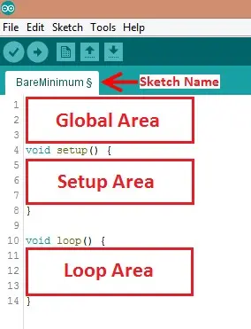
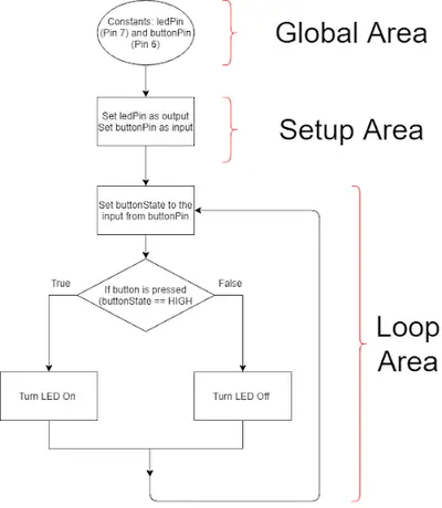
In Arduino, the term “sketches” refers to the programs written for the microcontroller. A basic Arduino sketch can be divided into three distinct sections: global, setup, and loop. These sections are illustrated in Figure 14.
– Global: This segment contains constants and imported libraries that are accessible throughout the entire sketch.
– Setup: The functions within the setup section are executed once at the beginning of the program. This section is commonly used to initialize pins and sensors in the program.
– Loop: The loop function runs continuously after the setup function has executed. The code within the loop function will continue to run until the Arduino loses power. It is often the most significant part of the program, responsible for reading data from sensors and controlling pins by toggling them between HIGH or LOW states.
Data Types
Data types in C++ represent the various kinds of data values that can be employed, manipulated, and stored. The fundamental and commonly used data types are illustrated in Table 1.
| Data Type | What It Stores (Examples) | Default Value | Notes |
|---|---|---|---|
| True value (1, HIGH) or false value (0, LOW) |
0, FALSE, LOW | – | |
| Integer number (e.g. -5, 15, 1047) | 0 | Positive or negative | |
| Decimal number (e.g. -0.5, 123.77) | 0 | Positive or negative | |
| Single character (e.g. ‘c’, ‘A’, ‘5’, ‘?’) | Indeterminate | Enclosed in single quotes | |
| Sequence of characters (e.g. “Hello World!”, “10”, “157+5”) | Empty (“”) | Enclosed in quotes |
Operators
Operators in programming are used to execute operations on variables and constants, and the outcomes of these operations are typically stored in a variable. Table 2 presents a list of commonly used operators.
| Operator | What it Does | Notes |
|---|---|---|
| = | Assigns a value to a variable | – |
| + | Adds two or more values | – |
| – | Subtracts two or more values | – |
| * | Multiplies two or more values | – |
| / | Divides two or more values | – |
| ++ | Increment by 1 | Usually used in loops |
| — | Decrement by 1 | Usually used in loops |
| == | Checks if two values are equal | Usually used in conditionals |
| != | Checks if two values are not equal | Usually used in conditionals |
| > or < | Less than, greater than comparison | Usually used in conditionals |
| <= or >= | Less than, greater than, or equal to comparison | Usually used in conditionals |
| && or || | Boolean AND or Boolean OR ssed to cascade multiple Boolean operations | Usually used in conditionals |
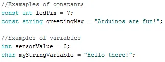
Constants and Variables
Constants and variables (Figure 15) are entities that store data based on their specified data type. To be referenced later in the program, they must be assigned a name. Constants hold data that remains unchanged throughout the program’s execution. Typically, constants store values like pin numbers or sensor threshold values. On the other hand, variables hold data that undergoes changes during the program’s runtime. They often contain sensor readings and other values that require mathematical operations. Figure 15 demonstrates how to create and utilize different constants and variables in a program.
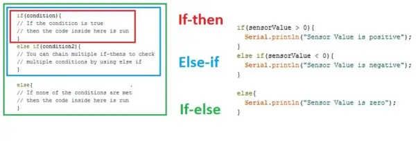
Conditional Statements
Conditional statements (Figure 16) run code enclosed by their curly brackets when a condition is met.
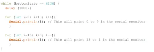
Loops
Loops are constructs in programming that execute the code enclosed within curly brackets repeatedly for a defined number of times or until a specified condition is satisfied.
While loops are employed to perform a task repeatedly until a condition is met. In Figure 17, the while loop executes its code only when the state of the button is HIGH. Once the button’s state becomes LOW, the while loop will cease to run.
Commonly Used Functions
Table 3 presents a collection of frequently utilized functions within the Arduino IDE that are specifically designed to interact with the digital and analog pins of the board. Digital pins on the board are capable of handling only two values: HIGH or LOW, either as inputs or outputs. In contrast, analog pins can process numerical values within the range of 0 to 1023.
| Function | What it Does |
|---|---|
| pinMode(pin, mode) | Sets a pin as an input or output |
| digitalWrite(pin, value) | Sets a digital output pin to HIGH or LOW |
| digitalRead(pin) | Reads a digital input pin as HIGH or LOW |
| analogWrite(pin, value) | Sets an analog output pin to a value 0-1023 |
| analogRead(pin) | Reads an analog output pin as a value 0-1023 |
| delay(milliseconds) | Pauses program for a certain amount of time |
| Serial.print(value) | Prints the value (variable) to the Serial Monitor |
Heat and Heat Transfer
Heat is a form of energy that can have both advantageous and destructive effects. For instance, the heat generated by the combustion of fossil fuels in an engine or the friction between engine components can lead to engine damage. In residential settings, heating, ventilation, and air conditioning (HVAC) systems maintain comfortable temperatures by either warming the home during colder periods or cooling it during warmer times. Many systems and devices integrate components and materials designed to either dissipate or retain heat within the system.
Heat transfer refers to the process of thermal energy moving from one body to another due to temperature differences. Temperature is a measure of the average kinetic energy of atomic motion, and higher temperatures imply faster atomic movement. The primary mechanisms of heat transfer are conduction, convection, and radiation.
Conduction occurs when there is a temperature disparity within a solid body or between solid bodies in contact. During conduction, heat energy flows from the region of higher temperature to the region of lower temperature. For example, consider a heated metal rod; the atoms within the rod collide at the point of temperature difference, facilitating the transfer of energy until the rod’s temperature equalizes.
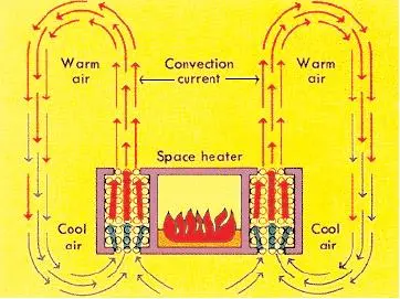
Convection, on the other hand, involves the transfer of heat within a fluid medium, encompassing gases and liquids. Convection can occur as either natural or forced. Forced convection, illustrated in Figure 19, takes place when external forces induce fluid movement, leading to heat transfer. Natural convection, however, arises from density differences in fluids, prompting the movement of liquids or gases due to temperature variations.
Radiation is the process by which energy in the form of electromagnetic radiation is emitted from a heated surface in all directions. Unlike conduction and convection, radiation does not require a medium to carry the energy. An example of heat transfer by radiation is the warming of the Earth by the Sun. Electromagnetic radiation is a means of energy transfer that occurs when an atom absorbs energy, and this energy can manifest as heat, light, ultraviolet, or other electromagnetic waves, depending on the type of atom and the amount of energy absorbed.
Color is a property of light. When an object appears white, it reflects virtually all the electromagnetic waves incident upon it, while a black object absorbs the waves. The color or reflectivity of materials is an essential consideration when selecting materials for thermal insulation.
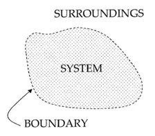
The container to be constructed in the lab is a thermodynamic system (Figure 20), which represents a portion of the Universe separated from its surroundings by an imaginary boundary. Thermodynamic systems can be classified into three types: open, closed, and isolated systems.
Open systems facilitate the transfer of both mass and heat. A classic example of an open system is a pot of boiling water. In this scenario, the pot interacts with the surrounding air, exchanging heat and water vapor. The water vapor, if collected, can condense back into liquid water with some mass.
On the other hand, closed systems solely allow the transfer of heat to the surroundings. An instance of a closed system is a hermetically sealed bottle of soda. When placed in a hot environment, the soda absorbs energy in the form of heat, but the liquid volume inside the bottle remains unchanged.
Isolated systems, in contrast, have no interaction with the surroundings whatsoever. They do not exchange heat or mass with the environment. While creating a perfectly isolated system is impractical, an ideal Thermos® approximates this concept. When hot chocolate is poured into a Thermos, the same amount at the same temperature will be poured out later.
Minimizing heat loss is a critical aspect in designing an effective insulating container. The choice of materials plays a key role. Opting for materials with poor heat conduction, like glass or certain plastics, helps reduce heat loss. Foam cups are made of plastic with tiny air bubbles suspended in them, utilizing air’s poor heat conductivity. The best insulator is a vacuum, which completely lacks air. Thermos® designs employ this principle to maximize insulation.
Additionally, the cost of creating the container is an essential consideration. A successful design aims to use minimal resources while maintaining product safety and efficacy.
Materials and Equipment
- Arduino UNO microcontroller and USB cable
- Computer with Arduino IDE
- Breadboard
- Jumper wires
- Resistors
- 220 Ω
- 10 kΩ
- 2.2 kΩ
- LED
- Push-button
- Thermistor
- Insulating Device Materials (Table 4)
Procedure
1. Building an LED Circuit and Button Circuit
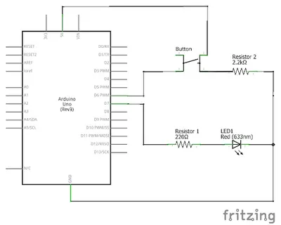
Part 1 of the project involves creating a circuit using an LED and a button. The desired behavior of the circuit is that the LED should illuminate when the button is pressed and turn off when the button is not pressed. Figure 21 displays the programming flowchart and the circuit diagram for this particular setup.
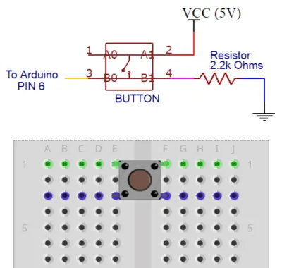
Before assembling the circuit on the breadboard, examine the bottom side (pin side) of the button to identify the pins and their connections. Take note of which pins serve as power, ground, and digital input into the Arduino. The push-button has an internal wire that connects the pins across its sides (as shown in Figure 23). When the button is not pressed, pins 1 and 2 are connected, and similarly, pins 3 and 4 are connected. It’s essential to ensure that the button is correctly positioned to bridge the gap between the electrical contact strips on the breadboard.
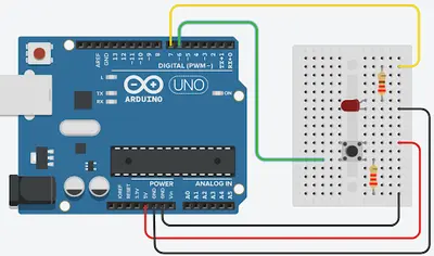
Construct the circuit on the breadboard following the circuit diagram in Figure 24. It is essential to remember that LEDs are polarized, meaning their orientation matters. Connect the shorter leg of the LED to the same row as GND. To prevent excessive current flow that could damage the LED, include a 220 Ω resistor in the circuit. Additionally, a 2.2k Ω resistor for the button is necessary to ensure a stable input. Carefully select and utilize the appropriate resistor for both the LED and the button to maintain the circuit’s functionality and avoid any issues.
To begin, initiate a new sketch in the Arduino IDE after connecting the Arduino/RedBoard to your computer. Open the Arduino IDE and navigate to Tools > Board > Select Arduino/Genuino Uno from the toolbar. Ensure you choose the correct port for your board by going to the toolbar and selecting the appropriate option.
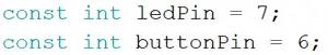
In the Global Area of the sketch, create the constants that will store the pin numbers for the button and the LED, as illustrated in Figure 25. These constants will be used in the program to maintain consistent pin assignments and improve code readability. To ensure that your code is approved by a TA, it is essential to include comments that explain the purpose of the code, allowing you and others to understand the logic and functionality of the program effectively.
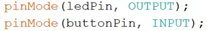
In the Setup Area of the sketch, employ pinMode() to configure the LED and Button. Set the LED to OUTPUT mode, as it will be controlled by the program. Meanwhile, set the button to INPUT mode, as the program will be obtaining data from the button, as depicted in Figure 26.
In the Loop Area, use digitalRead(), digitalWrite(), and a conditional to write the code that controls the button.
- Create a variable named buttonState, that will hold the input from the button (Figure 27).
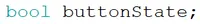
Use digitalRead() to set the buttonState variable to the current state of the button (Figure 28).
-

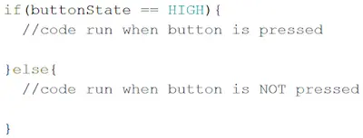
Figure 28: DigitalRead ButtonState Variable Set up the conditional statement that will be used to control the LED. In this code, the conditional is controlled by the button state (Figure 29).
-

Figure 29: Conditional Statement Use digitalWrite() to control the LED. Remember, we want the LED to be on when the button is pressed, and off otherwise.
- This line will turn the LED on (Figure 30).

Figure 30: LED On This line will turn the LED off (Figure 31).
-

Figure 30: LED OFF 2. Prototyping a Thermal Insulation Device
Competition Rules
The following rules must be observed at all times during the competition. Violation of any of these rules will result in disqualification.
- The placement of the thermistor with respect to the lid may not be changed
- The thermal insulating device may not be held while testing
- External heat sources are prohibited
- The jar of beeswax must be inside the container within 30 seconds of it being received
- The jar of beeswax cannot be returned (no restarts)
- A minimum of $0.40 must be used in the design of the insulating device
The competition will be judged by the minimal design ratio (MDR) (2) of the design. The design with the lowest MDR wins
(2) In (2), IC is the insulating capacity, Cost is the cost of the container, TR is the temperature of the room, and TF is the final temperature read by the thermistor. Ask a TA for the room temperature
The insulating container will be built using the materials in Table 4. Select the materials carefully. Consider their cost and their use as an insulator. Review the competition ratio before purchasing materials


- What is the primary purpose of the prototype?
To minimize the rate of heat loss from a container of heated wax using a TMP36 sensor and a microcontroller. - What sensor is used to measure temperature in the project?
The TMP36 sensor is used to measure temperature by converting voltage changes to temperature readings. - What microcontroller board is used in this lab?
An Arduino UNO compatible RedBoard is used as the microcontroller. - Which resistors are specified for use in the circuits?
The lab specifies 220 Ω, 2.2 kΩ, and 10 kΩ resistors. - How should the LED behave in the button circuit?
The LED should illuminate when the button is pressed and turn off when the button is not pressed. - What Arduino functions are suggested for reading the button and controlling the LED?
Use digitalRead to read the button and digitalWrite to control the LED, along with pinMode to set pin directions. - What factors should be considered when selecting insulating materials?
Consider materials' insulating properties (poor conductors like plastics or glass), reflectivity/color, vacuum effectiveness, and material cost. - What are key competition rules for testing the insulating device?
Rules include not changing thermistor placement relative to the lid, not holding the device during testing, no external heat sources, placing the beeswax jar inside within 30 seconds, no restarts, and using at least $0.40 of materials. - How is the competition judged?
By the minimal design ratio (MDR) which uses insulating capacity, cost, room temperature, and final temperature from the thermistor; lower MDR wins.