
Summary of PICCOLO Motor Controller Sample Design using TMS320F28023PT with Proteus Simulation
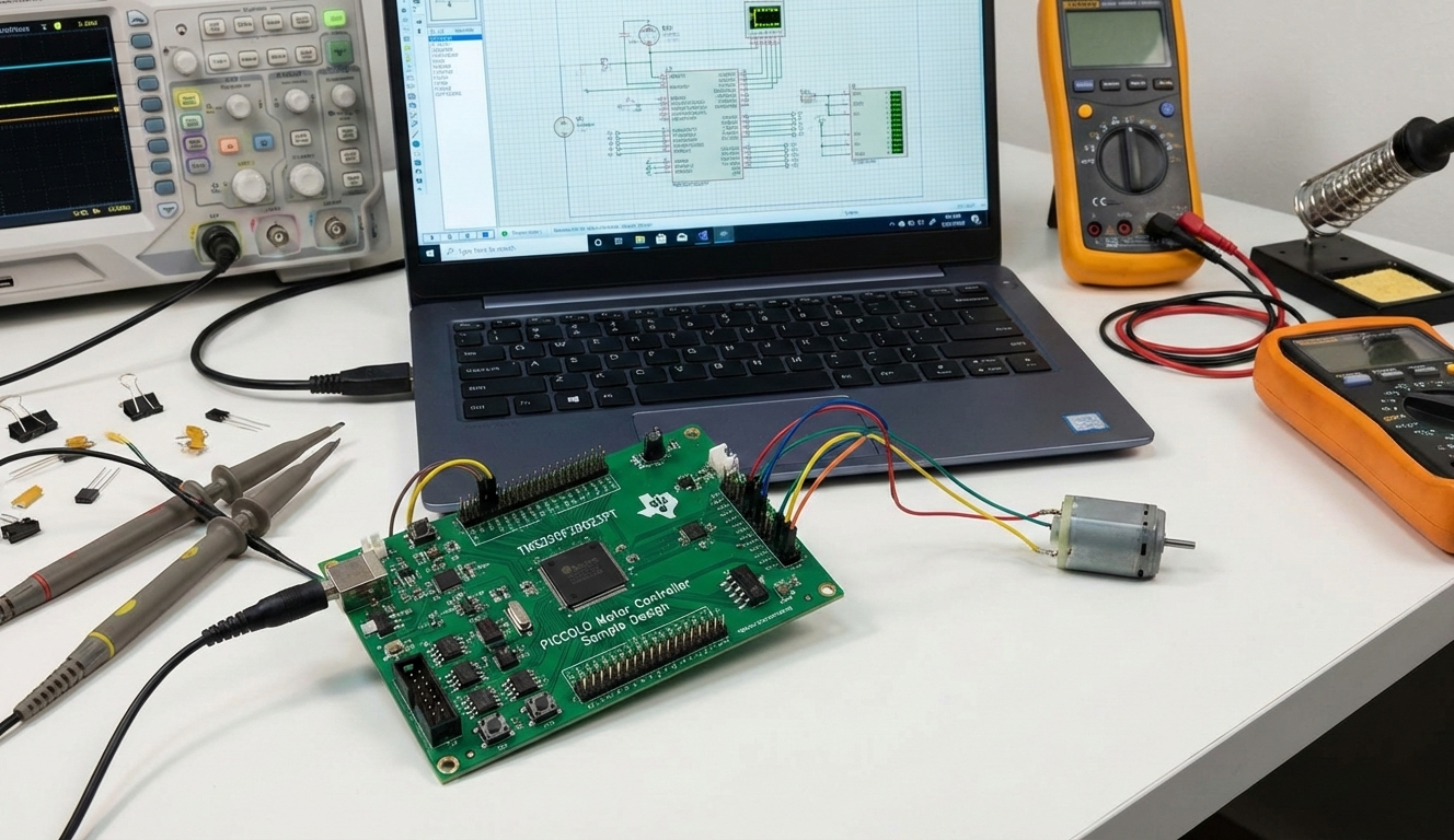
This project implements a PICCOLO motor controller sample using the TMS320F28023PT microcontroller and Proteus VSM, focusing on safe boot redirection, optional watchdog disable, C runtime initialization, and an accurate microsecond delay routine executed from zero-waitstate RAM for timing-critical motor-control firmware; it is suitable for simulation-based prototyping and embedded-systems learning.
Parts used in the PICCOLO Motor Controller Sample Design:
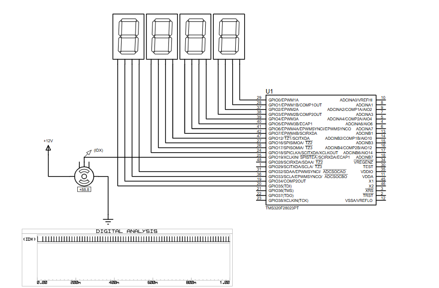
- TMS320F28023PT Piccolo microcontroller
- Seven-segment displays (simulation indicators)
- DC motor (simulation load)
- +12V supply (motor side)
- Proteus VSM digital analysis tools
- Can this project run entirely in Proteus without hardware?
Yes, the design is intended for full testing using Proteus VSM. - Why is the watchdog timer disabled?
To prevent unexpected resets during development and debugging. - Can the delay routine be used in other Piccolo projects?
Yes, it is reusable with proper CPU clock configuration. - Why must the delay function run from RAM?
To avoid wait states that would affect timing accuracy. - Is this project suitable for beginners?
It is best for users with basic knowledge of DSPs and embedded systems. - Can this be extended to real motor control hardware?
Yes, the startup and timing routines are directly applicable to hardware designs. - Which compiler is required?
CodeComposer Studio for Piccolo devices. - Can the watchdog be enabled later in the project?
Yes, it can be reconfigured once the system is stable.
