Summary of Microcontroller-Based Laser Pulse Code Detection: Harnessing Pulse Repetition Frequency
This paper presents a microcontroller-based Pulse Code Detection (PCD) system using a 4-quadrant laser detector and two ATmega32 MCUs to generate, decode, and lock onto laser Pulse Repetition Frequency (PRF) codes. A narrow gate and three-pulse detection reduce detection time and improve anti-jamming. The system is simulated in Proteus and implemented with QP50-6SD2 detector, laser diode, selector switches, servos for yaw/pitch, and confirms match between measured and simulated results.
Parts used in the Laser PCD System:
- QP50-6SD2 4-quadrant detector
- ATmega32 microcontroller (MCU1)
- ATmega32 microcontroller (MCU2)
- 16 MHz crystal oscillators (two)
- Laser diode (LD)
- Laser diode driver circuit
- Microcontroller programming card (ATmega32 development board)
- Selector/octal switches for code selection
- Servo motors for yaw and pitch control
- LED indicators (green and red)
- Oscilloscope (for pulse and gate measurement)
- Proteus VSM simulation software
- Power supplies: +5 V for MCU and LD, ±4.5 V to ±18 V bias for QD
This paper presents an enhanced system for detecting and tracking laser-guided weapons through a microcontroller-based decoding mechanism. The system utilizes a 4-quadrant laser detector to receive reflected pulses, and an electronic circuit processes these pulses. The processed data is then sent to a microcontroller for decoding the laser signal reflected by the target. The decoding system improves the accuracy of the laser seeker by reducing the time required for laser detection. This is achieved by minimizing the number of received pulses needed to detect the code and generating a narrow gate signal to enhance anti-jamming capabilities.
A laser pulse code detection (PCD) system model is implemented based on the Pulse Repetition Frequency (PRF) technique, involving two microcontroller units (MCUs). MCU1 generates laser pulses with various codes and communicates with switches to control the selected code. MCU2 recognizes the laser code and locks onto the system at the specific code. The locked frequency can be altered in both MCUs through switch selection. The system is simulated and tested using Proteus Software to assess laser code compatibility and rejection.
The implemented hardware concept is employed to evaluate the performance of the 4-quadrant detector with laser PCD. Testing includes assessing laser code compatibility, immunity to false laser codes, and laser code resolution. The results of the system tests demonstrate that the system can detect the laser code with only three received pulses, based on the narrow gate signal. The measured system performance aligns well with the simulated results, confirming the effectiveness of the proposed system.
INTRODUCTION
A 4-quadrant detector serves as an optical sensor widely employed in applications such as alignment, free-space optical communication, fiber optics measurements, and decoding laser receivers. Laser guided weapons (LGWs) have become increasingly significant in response to the growing demand for precision attacks. Among guided munitions, semi-active laser (SAL) guided weapons are frequently utilized on the battlefield, with considerable advancements in optoelectronic countermeasure development over the past two decades. From a humanitarian perspective, there is a universal desire for warheads to precisely hit their designated targets, minimizing harm to civilians [1]-[3].
The use of laser pulse codes represents an anti-jamming measure in SAL guidance systems technology. In this context, the laser decoding system integrated into weapons receives and processes pulse echoes reflected by the target surface. This process allows for the correction of the weapon’s trajectory, guiding it accurately towards the intended target.
The guided weapon possesses the capability to effectively target and secure a moving target. The functioning of LIDAR closely resembles that of traditional radar [4], [15]. Numerous patents in Pulse Code Detection (PCD) detail the advancement of Pulse Repetition Frequency (PRF) detection and lock systems [5], [6], [16]. The LGW locates the target by identifying the echo and subsequently tracks the direction of the laser echo with the highest intensity. Typically, a decoding system module is integrated into a small or medium-scale integrated circuit (IC), with the IC gradually being replaced by technology developed by a microcontroller unit (MCU).
LGWs utilize laser pulses with a specific code, generating a laser beam echo from the target within a designated gate window. The onboard circuit of the LGW detects this echo. These codes often take the form of a counter of the PRF per second. Upon detecting a lock pulse code, the tracking electronics circuit is instructed to track the target reflecting the laser beam energy with the locked pulse code.
In this study, an MCU is employed primarily to detect the locked pulse code and distinguish it from jamming pulse codes. False pulse codes may originate from jammers, buildings, tree reflections, or deliberately transmitted deceptive jamming pulse codes intended to misguide the missile.
The controller generates a command sequence for tracking purposes and communicates with the processing computer to load a negotiated code into the munition. The microcontroller plays a crucial role in the processing circuit, controlling and making decisions for the components. The system is equipped with switches that facilitate the selection of different codes.
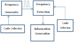
The user interface can be created through a PC serial interface and Proteus software comport interface. Figure 1 illustrates the proposed Pulse Code Detection (PCD) system block diagram. The organization of this paper is as follows: Section II discusses the proposed technique, including code algorithms and essential materials; Section III covers Proteus application and hardware implementation; Section IV presents simulations and results; and finally, Section VI provides the conclusion.
The implementation involves the use of the ATmega32 microcontroller, incorporating a real-time graphical display that controls two servo motors—one for yaw and another for pitch angles. Additionally, a system for multiple code selection using selector switches is modeled and implemented, generating various pulse codes to enhance the overall efficiency of the system.
- System Design
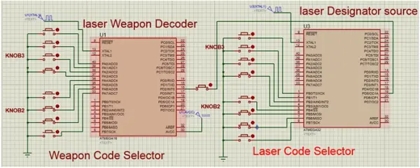
Two ATmega32 microcontrollers (referred to as MCU1/2) are employed to replicate the laser coding and tracking system. MCU1 generates laser pulses with various codes, adjusted by an octal switch to mimic the laser pulses present in the environment.
MCU2 is responsible for decoding the output pulse from the first microcontroller. It receives this pulse at the interrupt pin for simulation purposes. In one scenario, when the code matches the locked code in MCU2, the LED illuminates. In the alternate scenario, when the code differs from the locked code in MCU2, the LED remains off.
To generate TIMER1, two 16 MHz crystals are utilized. TIMER1 generates laser pulses for MCU1, enabling the production of pulse widths with different frequencies. The second crystal is employed by MCU2 to generate the gate for the decoder, distinguishing between the locked pulse and the pulse sent from MCU1.
2. PROPOSED TECHNIQUE
The LED status provides information: an illuminated LED indicates the same laser code, while an off LED signifies a different code. For simulation purposes, switches control the output code from MCU1 (laser designator). By changing the switch position, various Pulse Repetition Frequency (PRF) codes can be produced. MCU2 also features switches to simulate the locked code on the receiver. This diversity of codes allows the simulation of the system to test its ability to recognize true and false codes.
An oscilloscope is utilized to measure the pulse width and frequency of the specific PRF from microcontroller one. Additionally, it measures the gate produced by the second microcontroller.
TABLE I COMMUNICATION PROTOCOL BETWEEN SWITCHES AND
CONTROLLER
Octal switches Terminal display Function (1,1) 50ms ATmega Pin 18,19
(1,2) 50.800ms ATmega Pin 18,19
(1,3) 51.600 ms ATmega Pin 18,19
(1,4) 52.200 ms ATmega Pin 18,19
………… ………… …………
………… ………… …………
(8,8) 100.800ms ATmega Pin 18,19
B. Code Algorithm
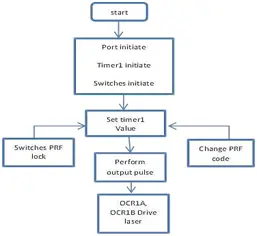
The majority of programming techniques operate in interrupt mode, as illustrated in Fig. 4, which depicts the algorithm code for Pulse Repetition Frequency (PRF) generation. This code generates signals with varying PRFs based on the code switch selector, and the pulse width is set to 500 ns at pins 18 and 19. By default, it produces a 20 Hz signal and can switch between different codes.
Fig. 4 presents the flow diagram for the frequency detection and information generation code algorithm, responsible for detecting PRF and information from various parts of the system, including the yaw/pitch angles of the servo motor. It also enables the system to lock onto different PRFs. Initially, the system is initialized and locked at 20 Hz. Subsequently, all interrupt priorities are set to high, except for the Timer1 interrupt, which is designated as a low-priority interrupt. Pulses from the first controller arrive at interrupt I0 at pin 16, continuously measuring the time between two pulses and calculating the frequency. Timer1 is utilized to measure the time period.
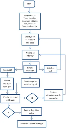
The Timer 1 prescaler is set to 1:64 to prevent timer overflow during low Pulse Repetition Frequencies (PRFs) measurements. A 16 MHz crystal is utilized, resulting in one step per clock (CLK) equivalent to 4 microseconds. For a desired timer period of 90000 microseconds, the calculation for OCR1A is performed as follows: OCR1A = 90000/4 = 22500 = 0x57E4-1 = 0x57E3.
The subsequent C code statements are employed for PRF calculation: timer value = (TMR1H*256 + TMR1L); time period = (timer value / 312500); frequency = (1 / time period). Here, TMR1H represents the timer1 high byte register, and TMR1L is the timer1 low byte register.
If the detected PRF matches the locked PRF, the LED status is turned ON; otherwise, it is turned OFF. Analog-to-digital conversion (ADC) interruption is employed to convert input analog voltage to digital voltage, mapping it to a -90° to +90° yaw/pitch servo motor gimbal angle. The weapon’s line of travel and its longitudinal axis are defined as the Yaw angle, while the pitch angle is the angle between the horizontal plane and the weapon’s longitudinal axis [10], [11].
Timer1 interrupt is utilized to generate a 30-microsecond pulse with a PRF equal to the input signal’s PRF at the interrupt pin, using a 1:64 prescaler to decrease the number of overflows. A serial interrupt is incorporated to display the locked PRF, detected PRF, yaw/pitch angles, and the locked PRF can be modified using code selector switches [10], [12].
To enhance anti-jamming performance, a gate signal is introduced to select the correct laser pulse in the decoding system, generating a fixed interval code in the laser target designator.
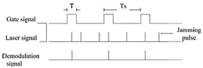
As illustrated in Figure 5, the gate signal is a generated signal mirroring the laser pulse signal transmitted by the laser designator. It shares the same period as the laser radiation. The decoding seeker receives both the reflected laser radiation from the target and any other laser radiation present. Utilizing the pulse width of the gate signal, the system discerns and rejects jamming signals while locking onto the authentic signal. A broader gate pulse width correlates with increased interference. Hence, to minimize the gate width of the laser pulse, mitigate jamming effects, and enhance system sensitivity, only three input pulses are employed for identifying the laser code. This process is carried out through the software code embedded in the seeker module.
3. HARDWARE IMPLEMENTATION
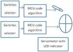
Figure 6 illustrates the block diagram depicting the envisioned design concept for the laser Pulse Code Detection (PCD) and recognition device. The configuration involves the utilization of the 4-quadrant detector QP50-6SD2 as the first sensor, a microcontroller programming card featuring ATmega32, and a laser diode (LD) necessary for simulating a laser target designator. The control of the laser diode driver is managed by an embedded circuit based on a microcontroller.
The system circuit is integrated with a practical selector switch, facilitating the adjustment of laser pulse codes [13].
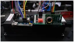
In Figure 7, a photograph depicts the prototype of the laser Pulse Code Detection (PCD) device. The hardware prototype has been constructed and assembled to conduct tests on laser PCD, aiming to distinguish between various laser pulses. The system comprises the QP50-6SD2, employed to bias the QD within the range of ±4.5 V to ±18 V, enabling it to enter the operational mode. Additionally, there is a microcontroller programming card operating at +5 V, an LD functioning with +5 V, and MCU driver along with selector switches.
4. SIMULATION AND RESULTS
Proteus Virtual System Modeling (VSM) is widely employed for simulation purposes [14], [17], [18]. Its spatial capabilities include the simulation of components, and the integration of a microcontroller facilitates the virtual testing of a system before its actual implementation. Utilizing the Proteus Transient analysis tool allows for the precise and accurate analysis of the frequency and width of various waveforms and signals.
The initial phase involves modeling a pulsed laser within a simulated environment. To achieve this, the ATmega32 microcontroller generates pulses with a 30-microsecond pulse width and Pulse Repetition Frequency (PRF) at different wavelengths based on the selection made using code switches. Figure 6 illustrates the output of the pulsed laser model in the Proteus VSM simulation, observable at microcontroller PIN 18,19.
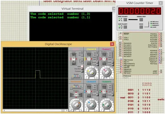
Various scenarios can be envisioned based on the detected PRF at the receiver and the locked PRF on the laser pulsed model. Although the system can be configured to numerous codes, for simulation purposes, it is examined under two specific PRFs: 10 Hz and 10.8 Hz. Consequently, four distinct cases are investigated.
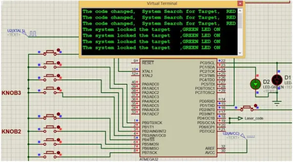
In one scenario, the detected frequency at the interrupt pin is 10 Hz, and the system is concurrently locked at 10 Hz. Since the locked Pulse Repetition Frequency (PRF) matches the detected PRF, the status green LED is illuminated, and the red LED is turned off, as illustrated in Fig. 6.
Similarly, in the second situation, when the switches are set to code 2 on the receiver, the system becomes locked at 10.8 Hz. Consequently, the status green LED turns off, and the red LED is switched on.
In the third case, with the select switch activated, the PRF generated becomes 10.8 Hz. As a result, both the detected PRF and the locked PRF are 10.8 Hz, causing the status green LED to turn on, and the red LED to turn off.
In the final case, choosing switch code 1 on the receiver locks the system at 10 Hz. Now, the detected PRF is 10 Hz, while the locked PRF is 10.8 Hz. Since these values differ, the status green LED turns off, and the red LED turns on.
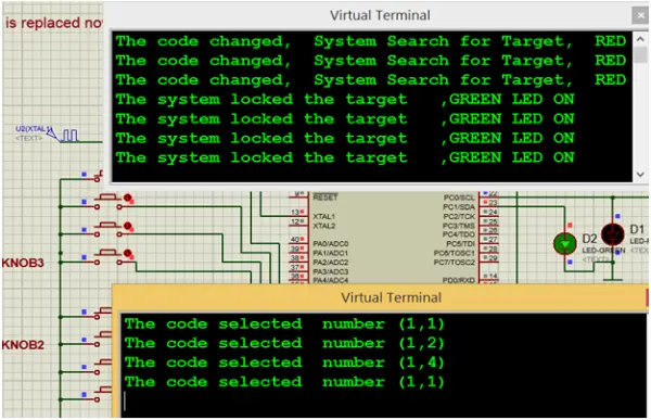
Figure 10 displays the virtual terminal output reflecting various inputs from the selected switches. When the select switch is set to ‘1’ on both the laser and receiver, it indicates the values of the detected PRF, locking the system at 10 Hz. Choosing a different code causes the system to lose track of the target and initiate a search anew.
Upon locking onto the target, the system processes data, calculates the position of the reflected beam’s laser, and then transmits digital OCR1A and B data to adjust the servomotor for YAW and PITCH, aligning with the target.
- How many pulses are required to detect the laser code in the proposed system?
The system can detect the laser code with only three received pulses based on the narrow gate signal. - Can the system change the locked frequency?
Yes, the locked frequency can be altered in both MCUs through switch selection. - Does the system improve anti-jamming capability?
Yes, by generating a narrow gate signal and minimizing required pulses, the system enhances anti-jamming performance. - What detector is used as the optical sensor?
The QP50-6SD2 4-quadrant detector is used as the optical sensor. - How is the laser pulse generated for simulation?
MCU1 (ATmega32) generates laser pulses with 30-microsecond pulse width and selectable PRFs using selector switches. - How does MCU2 recognize a matching code?
MCU2 measures the time between pulses at an interrupt pin to calculate PRF and compares it to the locked PRF; if they match, the LED turns on. - What software is used for simulation and testing?
Proteus Virtual System Modeling (VSM) is used for simulation and transient analysis. - What role do the selector switches play?
Selector switches select different PRF codes on both transmitter (MCU1) and receiver (MCU2) for testing compatibility and locking behavior. - How are yaw and pitch controlled in the system?
ADC converts input analog voltage to digital values mapped to -90° to +90° and drives servo motors for yaw and pitch control. - Do measured results match the simulations?
Yes, the measured system performance aligns well with the simulated results, confirming effectiveness.