Summary of External interrupt For CSS Compiler
This article presents C code for a PIC16F877 microcontroller that toggles PORTB pins: B6 blinks every second in the main loop, while B7 toggles in an external interrupt service routine triggered on a high-to-low edge. It configures ADC, fuses, clock, external interrupt, and I/O directions, enabling global and external interrupts. Useful for demonstrating interrupt-driven I/O and basic MCU initialization.
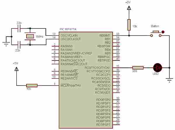
Parts used in the PIC16F877 External Interrupt Toggle Project:
- PIC16F877 microcontroller
- Power supply (suitable for PIC16F877 and XT oscillator)
- Crystal oscillator (XT) compatible with 4 MHz clock
- Pushbutton or external signal source to trigger external interrupt (RB0/INT)
- Pull-up or pull-down resistor for the external interrupt input
- LED for PIN_B6 (with current-limiting resistor)
- LED for PIN_B7 (with current-limiting resistor)
- Wiring/PCB or breadboard and connecting wires
- Programmer for PIC16F877
#include <16F877.h> #device adc=8 #fuses XT,NOWDT,NOPROTECT,NOLVP #use delay(clock=4000000)#INT_EXT void EXT_ISR(void){ output_toggle(PIN_B7); delay_us(300); } void Init_MCU(void){ enable_interrupts(GLOBAL); enable_interrupts(INT_EXT); ext_int_edge(H_TO_L); set_tris_B(0x01); output_low(pin_B7); } void main(){ Init_MCU(); while (TRUE) { output_toggle(PIN_B6); delay_ms(1000); } }
 #INT_EXT
void EXT_ISR(void){
output_toggle(PIN_B7);
delay_us(300);
}
void Init_MCU(void){
enable_interrupts(GLOBAL);
enable_interrupts(INT_EXT);
ext_int_edge(H_TO_L);
set_tris_B(0x01);
output_low(pin_B7);
}
void main(){
Init_MCU();
while (TRUE) {
output_toggle(PIN_B6);
delay_ms(1000);
}
}
#INT_EXT
void EXT_ISR(void){
output_toggle(PIN_B7);
delay_us(300);
}
void Init_MCU(void){
enable_interrupts(GLOBAL);
enable_interrupts(INT_EXT);
ext_int_edge(H_TO_L);
set_tris_B(0x01);
output_low(pin_B7);
}
void main(){
Init_MCU();
while (TRUE) {
output_toggle(PIN_B6);
delay_ms(1000);
}
}
- How does the code toggle PIN_B6?
The main loop calls output_toggle(PIN_B6) then delays 1000 ms, causing PIN_B6 to toggle every second. - How is PIN_B7 toggled?
PIN_B7 is toggled inside the external interrupt service routine EXT_ISR using output_toggle(PIN_B7) followed by delay_us(300). - What triggers the external interrupt?
The external interrupt is configured for a high-to-low edge using ext_int_edge(H_TO_L) on the INT_EXT interrupt. - How are interrupts enabled in the code?
enable_interrupts(GLOBAL) enables global interrupts and enable_interrupts(INT_EXT) enables the external interrupt. - What I/O direction is set for PORTB?
set_tris_B(0x01) sets PORTB direction with RB0 as input and other PORTB pins as outputs. - What clock frequency is the MCU configured for?
The code uses #use delay(clock=4000000) which sets the CPU clock to 4 MHz. - What fuses are defined in the code?
The fuses are XT, NOWDT, NOPROTECT, and NOLVP as specified by #fuses. - Is ADC enabled or configured?
#device adc=8 is present, indicating ADC resolution is set to 8 bits, but no ADC operations are used in the code.