Summary of Pitt Robotics Club’s Guide to PIC16F877A Programming
This tutorial explains wiring and programming a PIC16F877A on a breadboard, including power/regulator setup, pin functions (I/O, analog, PWM, serial), using crystal oscillator and capacitors, programming methods (CCS compiler, ICD-U40, PicKit 2), debugging tips, and example circuits and code for an LED blinker and photoresistor inputs.
Parts used in the PIC16F877A Tutorials:
- PIC16F877A microcontroller
- Breadboard
- Power supply or battery
- 7805 voltage regulator
- Wires (red for power, black for ground, others for signals)
- 47k resistor
- 1k resistor (for photoresistor circuit)
- Photoresistor (LDR)
- Crystal oscillator (20 MHz recommended)
- Capacitors (for power decoupling and crystal)
- LEDs
- Current-limiting resistor for LED (220–1k ohm)
- ICD-U40 or PicKit 2 programmer
- USB mini cable (for PicKit)
- Compiler/software (CCS PCW Compiler, CCSLoad)
The tutorials assume a foundational understanding of programming and electronics. If you’re new to programming, it’s advisable to grasp the basics of C or C++. Additionally, a basic knowledge of electronics and constructing simple circuits is recommended.
Most of this information was gathered from the PIC MCU Compiler reference manual, supplemented by input from other club members. You’re encouraged to modify or create new tutorials. Please contact the club via email if you generate another tutorial.

How to hook up the PIC so it will run?
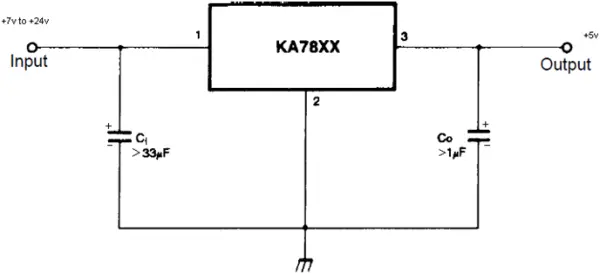
• When operating with a higher voltage supply, it is necessary to employ a voltage regulator to convert the elevated voltage to 5 volts. Usually, a 7805 regulator is utilized for this purpose. You can find the datasheet by searching on Google for “7805 voltage regulator.”
• If you’re unfamiliar with the functionality or appearance of these materials, consider researching them online.
Circuit
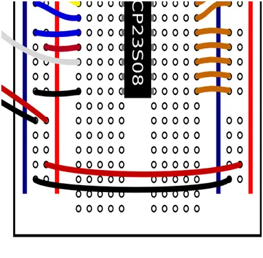
1. Place the PIC on the breadboard according to the pin diagram provided above for pin numbers. For clarity, align the PIC so that the dimple faces the same direction as indicated in the pin diagram.
2. Establish connections between the side strips of the breadboard – connect power to power (red strips) and ground to ground (black strips), mirroring the bottom two wires below. These strips are now denoted as “power” and “ground.”
3. Connect the power (Vpp) to Pin 1 via a red wire, utilizing a 47k resistor in between.
4. Attach the power (Vdd) to Pin 11 using a red wire.
5. Ground Pin 12 (Vss) by connecting a black wire.
6. Apply power to Pin 32 (Vdd) through a red wire.
7. Ground Pin 31 (Vss) with a black wire.
8. Connect the Crystal Oscillator to Pins 13 and 14 (OSC1, OSC2). The polarity isn’t significant (polarity refers to which of the two wires goes into which hole).
9. Insert a capacitor between power and ground, ensuring correct polarity as per the capacitor datasheet to prevent circuit damage.
10. Connect ground to the battery ground (-) using a black wire.
11. Link power (red) to the battery’s power (+) using a red wire. Alternatively, solder the wire to a switch and run another wire from the switch to the battery power, allowing power control.
If employing a voltage regulator:
– The raw battery power wire is directed to the voltage regulator input.
– The breadboard ground strip should be connected to the battery ground.
– The voltage regulator output wire (+5 volts) should be linked to the breadboard power strip.
– Connect the voltage regulator ground wire to the breadboard ground strip.
What do the pins mean?
The pins RB0-RB7, RC0-RC7, and RD0-RD7 function as digital I/O pins. CCP1 and CCP2, positioned alongside RC1 and RC2, are capable of generating a PWM signal (refer to the DC Motor tutorial). The AN0-AN7 pins are designated for analog I/O purposes (refer to the Photoresistor tutorial). TX and RX serve as I/O pins for debugging (refer to the Output Messages to Computer tutorial). The remaining pins manage power/ground, the clock signal, and programmer I/O.
A PIC consists of multiple “ports.” Each port is represented by a letter. RB0-RB7 form a port, as do RC0-RC7 and RD0-RD7. RA0-RA5 and RE0-RE2 are also ports, albeit with fewer pins. While some of these pins have specific roles, most can function as basic input/output pins.
Consider configuring pin RB0 as either an input or an output. When set as an input, it reads the digital voltage present on the pin. For instance, if RB0 connects to ground (0V), it would read as a digital 0. Conversely, if RB0 were linked to a power source (5V), it would read as a digital 1.
Alternatively, if configured as an output pin, RB0 can be set to output either 5V or 0V. This functionality allows actions such as switching an LED on or off, or controlling a motor.
How to program the PIC?
I refrain from providing detailed step-by-step instructions on programming the PIC because software tools tend to undergo frequent changes.
As of spring 2010, our club utilizes software offered by CCS (http://www.ccsinfo.com/). We rely on the PCW Compiler for writing and compiling programs. Additionally, we use CCSLoad and the ICD-U40 programmer to transfer programs to the PIC. Always load a .hex file onto the PIC, which represents the compiled machine language program. Ensure the .hex file is situated in the same folder as your project file.
Don Crouse, the president in 2010, created customized programming boards for that purpose. These boards might still be available in the lab. Another option is to splice the wires on an Ethernet cable and link them to the correct pins on the breadboard. If you prefer not to create your own device, you have the option to purchase the necessary components for programming the PIC.
The Pitt Robotics Club might have also had access to another programmer called the PicKit 2. To program using the PicKit, link the pin indicated by the arrow on the PicKit device to the MCLR pin. The pin next to the arrow, Pin 2, signifies +5 volts. Pin 3 is Ground (Gnd), Pin 4 is B7, Pin 5 is B6, and Pin 6 is the optional debug pin PGM (connecting this pin isn’t necessary). Additionally, make connections for power and ground (Vdd/Vss pins) on the PIC.
For PIC programming, connect the PIC IC to the PicKit and use a USB mini cable from the PicKit to the computer. To utilize the PicKit, launch the PicKit V2 program from the PC desktop. If the PicKit is set up to program a different PIC than your own, the first crucial step is selecting the PIC family. For the 16f877A, opt for “base device” in the device options.
To program a hex file, it must be loaded or imported initially. Achieve this by navigating to the file menu and importing your program’s hex file. Once the file is imported, proceed to click on the “write hex” button. This action should write your hex file and display a success message stating that it has been programmed. Note that the program will automatically initiate unless the /MCLR checkbox is selected and remains unchecked.
Please note: The PicKit can provide power to the PIC through the USB bus. It automatically identifies whether the device is powered during programming. If you prefer to run your PIC solely from the USB, you can choose the “VddOn” checkbox. This option can supply up to 1A of current at 5V. Ensure that the voltage number adjacent to the checkbox is set to 5, unless your processor does not support 5V. The PIC utilized in this tutorial operates at a 5V voltage level.
Miscellaneous Advice
Ensure the PIC is properly wired and set up for compiling and loading programs to proceed with the other tutorials.
To run the additional tutorials, adhere to these steps:
1. Set up the circuit as instructed.
2. Compile the example code using your preferred compiler.
3. Load the program onto the PIC.
4. Activate the power to execute the program.
In case you encounter coding issues, refer to past PIC code stored on the robotics lab’s computers. Often, similar programming challenges arise repeatedly, particularly concerning sensor input and motor output. It’s likely that someone has already addressed these challenges. You may also find the PIC MCU C compiler manual a helpful resource.
For a more organized setup, aim for neatness when connecting wires and components. Trim wires to lie flat on the breadboard without protruding. Ensure that the bare ends are sufficiently long to establish a secure connection with the breadboard. Maintain orderliness when arranging wires for various sensors, motors, switches, and lights, preventing a tangled mess as you add components.
Consistency in wire colors is a good practice. For instance, use the same color (typically black) for wires connected to ground. Employing consistent color codes allows for easy identification and understanding of wire functions, particularly when managing a substantial number of wires on the board. I use red for power (+ on the battery and breadboard), black for ground (-), blue for inputs, and green for outputs.
Always double-check your connections before flipping the switch. A single misplaced wire can potentially disrupt your circuit or cause damage.
You can build your circuit with test LEDs to ensure its functionality upon activation. Include a power light directly connected to the battery to indicate when the circuit is on. Additionally, use an LED controlled by the PIC. Programming the PIC to illuminate this LED upon starting ensures the PIC is functioning correctly.
The LED’s Anode should be connected to the +5V rail coming from the regulator. Meanwhile, the Cathode should be linked to a current-limiting resistor, which can have a value between 220 and 1k ohms. The other terminal of the resistor should connect to Ground. Upon circuit activation, this LED is expected to illuminate at its maximum brightness. In case the LED fails to light up, it could be inserted incorrectly. If you suspect the LED is misaligned and it either doesn’t illuminate or shines dimly upon powering up the circuit, TURN OFF YOUR CIRCUIT and recheck the wiring. This scenario commonly indicates a potential short circuit within your power connections.
If you’ve been using the robot for an extended period, it’s advisable to verify the voltage level of the power battery. Low voltage may cause erratic behavior in the robot due to a “brownout” situation, caused by the PIC experiencing a low voltage supply.
LED Blinker
Code
//allthese#belowsetupthePIC#include<16F877A.h>
#deviceadc=8
#FUSESNOWDT //NoWatchDogTimer#FUSESHS //Highspeed Osc > 4mhz#FUSESPUT //Power Up Timer
#FUSESNOPROTECT//Codenotprotectedfromreading#FUSES NODEBUG//No Debug mode for ICD
#FUSESNOBROWNOUT//Nobrownoutreset
#FUSESNOLVP //Nolowvoltageprgming,B3(PIC16)orB5(PIC18)usedforI/O#FUSESNOCPD //No EE protection
#usedelay(clock=20000000) //Setscrystaloscillatorat20megahertz#use rs232(baud=9600, xmit=PIN_C6, invert) //Sets up serial port output pin & baud rate
//mainprogramstartsherevoid main() {
//Infiniteprogramloopstarts.LEDblinksforever.while(true){
output_high(PIN_B7);//senda“1” topinRB7,makingRB7“High”at 5v
//thiswillturnontheLEDhookedtoRB7
delay_ms(500); //wait half a second, delays for 500msoutput_low(PIN_B7);//senda“0”topinRB7, makingRB7“Low”at0vdelay_ms(500); //wait half a second, delays for 500ms
}
}
Photo resistor Input
Circuit from the “Introduction to the PIC16F877A”:
Photoresistor
Use a 1Kohm resistor, or select an appropriate resistor for your photoresistor wiring.
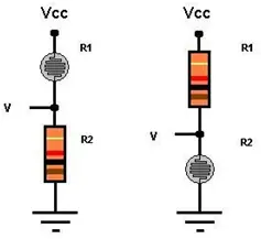
1. Connect the breadboard power (Vcc) to a 1K-ohm resistor.
2. Link the 1K-ohm resistor to the photoresistor power.
3. Connect the photoresistor ground to the breadboard ground.
4. Wire from between the resistor and photoresistor to the PIC pin AN0.
When R1 represents the photoresistor, the voltage rises as the light intensity increases. If R2 signifies the photoresistor, the voltage decreases as the light intensity rises.
Code for single photo resistor
//allthese#belowsetupthePIC#include<16F877A.h>
#deviceadc=8
#FUSESNOWDT //NoWatchDogTimer#FUSESHS //Highspeed Osc > 4mhz#FUSESPUT //Power Up Timer
#FUSESNOPROTECT//Codenotprotectedfromreading#FUSES NODEBUG//No Debug mode for ICD
#FUSESNOBROWNOUT//Nobrownoutreset
#FUSESNOLVP //Nolowvoltageprgming,B3(PIC16)orB5(PIC18)usedforI/O#FUSESNOCPD //No EE protection
#usedelay(clock=20000000)//crystaloscillatorat20000000hertz
#users232(baud=9600,xmit=PIN_C6,invert)//serialportoutputpin&baudrate
//runphotoresistorsignalwiretopinAN0
//connectLED/resistortopinRB7
voidmain(){
int16 photo=0;//16bitinteger,saferthanusingint because
//intisonly8 bitwhichmightleadtooverflowproblemsforadd,multiply
setup_adc(ADC_CLOCK_INTERNAL);//configureanalogtodigiralconverter
setup_adc_ports(ALL_ANALOG);//setpinsAN0-‐AN7toanalog(canreadvaluesfrom0-‐255insteadofjust0,1)
while(true){ //loop foreverset_adc_channel(0);//setthepictoreadfromAN0
delay_us(20);//delay20microsecondstoallowPICtoswitchtoanalogchannel0photo=read_adc(); //read input from pin AN0: 0<=photo<=255 //turnonLEDwheninput>127,elseturnoff LED
//Putfingeroverphotoresistor&takeitofftoseeLEDturn on/off
//127maynotbetheactualvaluethatseparateslightfromdark,sotrydifferentvalues
if(photo > 127){output_high(PIN_B7);
}
else{
output_low(PIN_B7);
}
}
}
Code for multiple photo resistors
//allthese#belowsetupthePIC#include<16F877A.h>
#deviceadc=8
#FUSESNOWDT //NoWatchDogTimer#FUSESHS //Highspeed Osc > 4mhz#FUSESPUT //Power Up Timer
#FUSESNOPROTECT//Codenotprotectedfromreading#FUSES NODEBUG//No Debug mode for ICD
#FUSESNOBROWNOUT//Nobrownoutreset
#FUSESNOLVP //Nolowvoltageprgming,B3(PIC16)orB5(PIC18)usedforI/O#FUSESNOCPD //No EE protection
#usedelay(clock=20000000)//crystaloscillatorat20000000hertz
#users232(baud=9600,xmit=PIN_C6,invert)//serialportoutputpin&baudrate
//readinputfrom3photoresistors
//runphotoresistorsignalwirestopinAN0,AN1,AN2
voidmain(){
int16 photo0=0;//16 bitinteger,saferthanusingint
//intisonly8bitwhichmightleadtooverflowproblemsforadd, multiplyint16 photo1=0;
int16 photo2=0;
setup_adc(ADC_CLOCK_INTERNAL);//configureanalogtodigiralconverter
setup_adc_ports(ALL_ANALOG);//setpinsAN0-‐AN7toanalog(canreadvaluesfrom0-‐255insteadofjust0,1)
while(true){ //loop foreverset_adc_channel(0);//setthepictoreadfromAN0
delay_us(20);//delay20microsecondstoallowPICtoswitchtoanalogchannel0photo0=read_adc(); //read input from pin AN0: 0<=photo<=255 set_adc_channel(1);//setthepictoreadfromAN1delay_us(20); photo1=read_adc(); set_adc_channel(2);//setthepictoreadfromAN2delay_us(20); photo2=read_adc(); //Youcouldadd3LEDs andturnthemonifphoto0/1/2>127
//justaswithcodeforsinglephotoresistor
}
}
- How do I power the PIC from a higher voltage supply?
Use a 7805 voltage regulator to convert the higher voltage down to 5 volts and wire regulator input to battery, regulator output to breadboard power, and regulator ground to breadboard ground. - How should the PIC be placed on the breadboard?
Place the PIC according to the pin diagram with the dimple oriented as shown, and connect breadboard power and ground rails to the PIC power and ground pins. - What pins provide analog input for sensors?
AN0 through AN7 are designated for analog I/O and are used for photoresistor inputs in the tutorial. - How is an LED connected to test the PIC?
Connect the LED anode to the +5V rail, the cathode to a current-limiting resistor (220–1k ohm), and the other end of the resistor to ground; a PIC-controlled LED is connected to a PIC output pin like RB7. - How do I program the PIC using a PicKit 2?
Connect PicKit pins to the PIC (arrow pin to MCLR, pin 2 to +5V, pin 3 to Gnd, pin 4 to B7, pin 5 to B6), attach USB mini cable to the PC, select the PIC device in the PicKit software, import the .hex file, and click write hex. - Can the PicKit supply power during programming?
Yes; enable VddOn in the PicKit software to supply up to 1A at 5V and ensure the voltage is set to 5V for this PIC. - What oscillator settings are used in the example code?
The examples use a 20 MHz crystal oscillator (use delay(clock=20000000) in code). - How do I read a photoresistor with the PIC?
Wire the photoresistor and a 1k resistor as a voltage divider between Vcc and ground, feed the divider midpoint to AN0 (or AN1/AN2), configure ADC and read values with read_adc after setting the ADC channel. - What should I check if the PIC circuit behaves erratically?
Check wiring, battery voltage for brownout, ensure proper ground connections, and verify the regulator and power rails are correct. - How do I enable analog inputs in code?
Use setup_adc(ADC_CLOCK_INTERNAL) and setup_adc_ports(ALL_ANALOG) to set AN0–AN7 as analog inputs before reading with read_adc.