Summary of Transform Your Home into a Smart Haven with DIY Wireless Automation
Smart Sitter is a low-cost DIY smart home system integrating PIR motion detection, MQ-2 smoke/gas sensing, LM34 temperature sensing, a Peltier thermoelectric climate module with H-bridge control, and XBee RF links to a user computer. A Tiny Real Time kernel coordinates tasks, debounced FSMs manage alerts, and the MCU drives an LCD, UART, and a 555-driven buzzer. The design emphasizes affordable, modular hardware with software-heavy integration to provide remote status, alerts, and temperature control under $100.
Parts used in the Smart Sitter:
- PIR motion sensor
- 555 timer chip (for buzzer, 2 kHz)
- Buzzer
- MQ-2 gas and smoke sensor
- LM34 analog temperature sensor
- Peltier thermoelectric device (TEC)
- H-bridge controller (for Peltier polarity/current)
- Independent 1 A power source (for Peltier)
- Microcontroller unit (MCU) with ADC and UART
- XBee transmitter and receiver modules (802.15.4)
- LCD display
- Serial interface software (CoolTerm referenced)
- Tiny Real Time multitasking kernel (software)
- Miscellaneous passive components and wiring for circuit schematic
Introduction
Smart home technology has grown tremendously in popularity over the last decade. A recent survey found that 46% of consumers view smart home features as an important consideration for their current or future residence. However, many commercial smart home systems are quite expensive to implement and require ongoing third-party monitoring fees. We sought to design an affordable alternative that homeowners could independently build and manage for under $100.
![]()
Our project consisted of several essential subsystems. A PIR motion sensor subsystem detected intruders and triggered an alarm buzzer via a 555 timer circuit. A smoke detector monitored for propane, hydrogen, methane, butane and smoke – common indoor safety hazards. Small-scale climate control was provided via a temperature sensor and Peltier module. Wireless RF transmitters allowed all subsystems to interface with a central microcontroller for remote home status polling, intruder/smoke alerts, and temperature adjustment within 100 meters of the residence. Due to the multifaceted nature of the integrated system, we employed a multitasking kernel to oversee coordinated operations. Our low-budget design aims to make smart home capabilities financially accessible through a do-it-yourself approach.
High Level Design
Rationale and Sources
Our goal for this final project was to design an application useful in daily life. As more consumers explore smart home technologies to increase convenience, we recognized that an expensive proprietary system isn’t necessary. Many helpful functions can be built affordably. We determined motion detection, smoke alarms, and climate control were essential for a basic smart home.
Modern interconnection through devices and the “internet of things” facilitates remote control from anywhere. To benefit from increased smartphone and wireless connectivity, we aimed to design our Smart Sitter system for wireless interaction from any location.
For climate control, we explored heating and cooling approaches. While a coil/fan could increase temperature, only passive dissipation was possible for cooling back to ambient. Designing an air conditioner/compressor was impractical at low cost. Investigating alternatives introduced Peltier thermoelectric devices, which transfer heat between sides using electricity in a solid-state pump. By adjusting current direction, the hot/cold faces can vary, enabling sub-room temperatures without compressors. Using a Peltier module grants temperature modulation accessibility within our design constraints.
Logical Structure
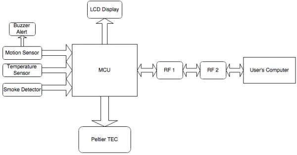
Our system’s logical architecture contains four primary subsystems all interfacing with the central MCU: a PIR motion sensor, temperature sensor, thermoelectric module, and smoke detector. On the highest level, the system interacts bidirectionally through RF transmitters between the MCU and the user’s computer.
This modular design permitted independent development, testing and troubleshooting of each subsystem in both the hardware and software domains. Once validated individually, integration joined the discrete pieces into a cohesive whole.
The block diagram below depicts the full system configuration. Breaking the project into defined blocks optimized the workflow, allowing focused effort on particular functions while maintaining a high-level view of interconnections. This structural partitioning streamlined the division of labor and facilitated iterative improvements to individual subsystems prior to amalgamation into the ultimate goal of an integrated smart home application.
Each subsystem consists of discrete hardware and software elements. In software, individual tasks running under the Tiny Real Time multitasking kernel control each subsystem’s operation. Tasks contain dedicated code and use semaphore locks to access variables shared between tasks, respecting deadline and release times.
As the block diagram illustrates, the motion, temperature, and smoke detectors transmit data to the MCU. It then processes the incoming information to set the LCD display and transmit readings over RF to the user’s computer. For simplified design, the buzzer circuitry directly responds to the motion sensor output.
To govern climate control, the MCU receives the target temperature from the RF module connected to the computer. It analyzes input from the temperature sensor against the goal, setting the Peltier TEC’s current direction as needed to raise or lower the ambient setting. This system architecture decomposes each component for discrete yet synchronized function under a unified kernel, leveraging hardware-software codesign principles to achieve an integrated smart home solution.
Hardware and Software Tradeoffs
We opted to realize more intricate elements through software to accomplish our goals within budget and timeline. Off-the-shelf purchases like the PIR sensor, H-bridge controller, and timer circuitry allowed focus on multilayered interactions through code versus custom hardware. Throughout the process, few tradeoffs between hardware/software design arose. One instance involved temperature sensing – while our plan specified a digital sensor, its hardware proved quite complex to implement correctly. Therefore, we switched to an analog model instead, prioritizing manageable software complexity over hardware intricacy. Though this increased coding work for temperature monitoring, balancing hardware/software complexity represented an expedient design choice versus exceeding constraints. Though some prebuilt components minimized fabrication efforts, software implementation united discreet parts into a cohesive automated system utilizing our multitasking approach.
Standards
The smoke detector integrated within our system complies with Underwriters Laboratory specifications UL217 and UL268. UL268 sets requirements for smoke detectors and guards used in ordinary indoor spaces according to the National Fire Alarm Code NFPA 72. UL217 covers electrically operated single and multiple station smoke alarms for open area protection in indoor residential units per NFPA 72 as well as smoke alarms for recreational vehicles per NFPA 501C, recreational boats per NFPA 302, and detached homes/townhouses according to the International Residential Code. Portable alarms are also covered under UL217.
Our C code adhered to standards set by the American National Standards Institute (ANSI) for the C programming language.
The XBee transmitter and receiver modules used wireless transmission following Federal Communications Commission regulations.
Intellectual Property
Our project utilizes the open-source Tiny Real Time multitasking kernel developed by Dan Henriksson and Anton Cervin. We also employed Roger Meier’s freely available open-source CoolTerm serial communication interface program. Aside from these, our design contains no other elements that potentially infringe upon others’ intellectual property or patents. Specifically, passive infrared sensing, resistance-based smoke detection, and Peltier thermoelectric technology are non-proprietary building blocks seen across many commercially available consumer systems. As these core components lack copyright restrictions, and we properly utilized the open operating system and serial interface under their public licenses, our work avoids issues of intellectual property infringement present in some technical research domains.
Program/Hardware Design
Passive Infrared Motion Sensor
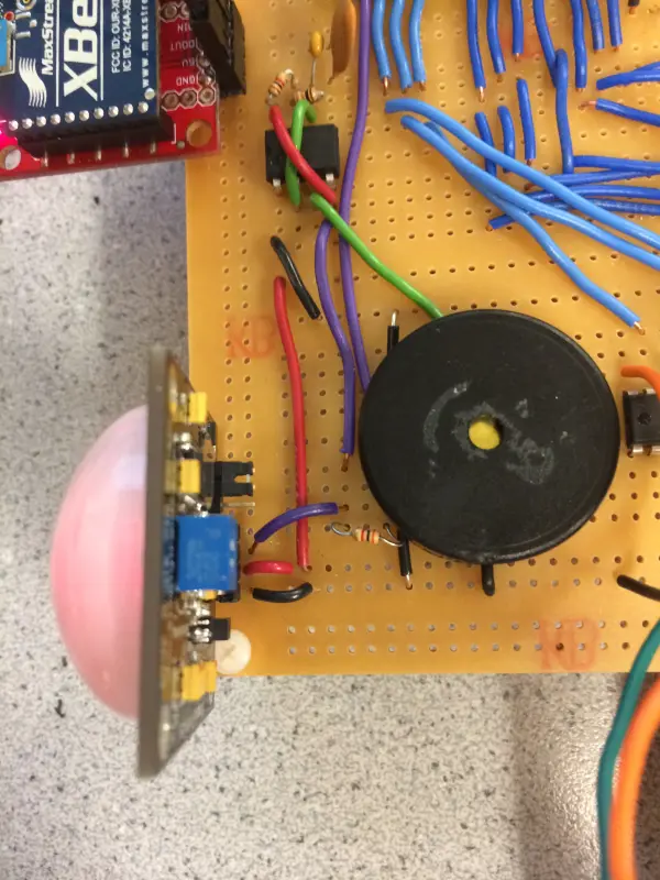
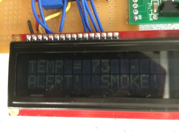
The motion detector subsystem utilized a Passive Infrared (PIR) sensor that outputs a digital high signal (5V) to the MCU upon motion detection. This input triggers an alert, displaying “ALERT!” on the LCD until motion ceases. Wireless XBee transmission also relays the alert signal to the user’s PC. The sole limitation of the PIR sensor is a 40 second warm-up period to acclimate. Additionally, the 5V pulse actuates a buzzer for audible signaling via a 555 timer chip oscillating at 2kHz. As shown in the image, the PIR subsystem implements basic motion sensing and alert functions through integration of affordable, readily available components.
Climate Control and Temperature Sensor
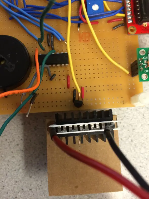
The climate control and temperature subsystems closely interacted. A LM34 analog sensor measured temperature via its 10mV/°F output voltages. The MCU’s internal ADC converted this to a digital reading using its 2.56V reference and 8-bit resolution after left-shifting.
Temperature data informed climate control via a Peltier thermoelectric device (TED). As a solid-state heat pump, the TED transfers heat between sides per current direction. An H-bridge switched polarity to selectively heat or cool the sensor side. Generating 1A required an independent power source.
To instruct climate settings, the user inputs a target temperature via the computer’s serial interface. The XBee network relays this value to the MCU’s UART. It then checks the sensor reading, determining if current conditions are higher or lower than desired. Based on this analysis, the MCU commands the H-bridge to appropriately enable the TED, cooling or heating as needed via current flow adjustments. This integrated approach achieved distributed sensing and climate regulation under remote supervision. The subsystems are diagramed below, showcasing their combined role in environmental modulation.
Smoke Detector
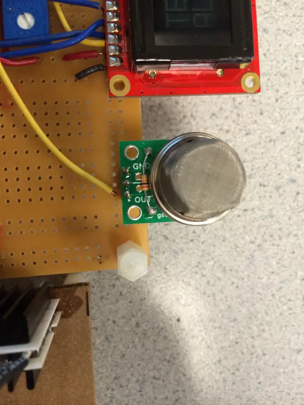
The smoke sensor subsystem utilized an MQ-2 flammable gas and smoke detector. Measuring from 300-10,000 ppm, it is highly sensitive to LPG, propane and hydrogen. The sensor converts conductivity changes to an output representing gas concentration.
Its major limitation was a 48-hour warm-up period. The analog output connected to an MCU ADC pin for digitization. Through experimentation, we established a threshold indicating combustible gas detection. Upon exceeding this value, a smoke alert signal triggered display of “SMOKE!” on the LCD and wireless transmission to the user’s computer.
As shown, the subsystem integrates the affordable MQ-2 into our design for basic smoke detection functionality. Analog conversion and programmed logic analyze sensor output to identify hazardous conditions and alert the remote user when needed for enhanced safety monitoring.
LCD and UART Interfaces
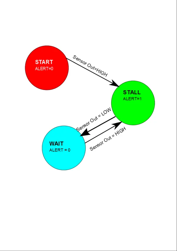
To reliably update the UART interface and LCD display only when intrusions/smoke were detected, debouncing the alert signals was necessary. This ensured a single static alert message remained visible for an appropriate duration.
Finite state machines provided signal conditioning for the motion and smoke subsystems. Each monitored the respective sensor output, changing an alert variable upon detecting a high signal. This triggered display of the corresponding message on LCD and UART.
The machines then stalled in a waiting state until the sensor output fell low. This hold period allowed sufficient read/response time before re-triggering. Once back low, the alert variable reset to ready the next detection.
By integrating finite state logic, transient signals didn’t erroneously induce false alerts or rapid flickering. Only sustained high readings escalated notifications, maintaining a clear singular issue presentation until resolved for both local and remote users through a simplified interface.
Wireless Communication
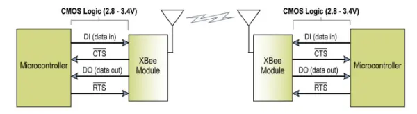
Wireless functionality relied on RF communication between the primary unit and user’s computer via a pair of XBee modules adhering to the 802.15.4 protocol. Data packets transmitted serially between the devices.
Their serial interfaces facilitated connection to any UART-compatible logic. As illustrated, one XBee received data from the MCU for output. The other interfaced with the computer, sending inbound information.
This arrangement distributed sensing and control through a standardized wireless protocol. By integrating affordable, readily available XBee modules, remote monitoring and adjustment became possible – a key aim in developing this smart home solution. The modular design also promotes extendibility to additional remote devices maintaining simple serial interoperability.
We configured our XBee modules following guidance from Digi documentation, issuing system commands to define each in the radio network. Specifically, we established a point-to-point setup between the MCU and computer as their example outlined. However, XBee also enables point-to-multipoint communication should the application demand multiple interconnected units.
Addressing remains a consideration, as the finite set must not duplicate. However, interference was negligible in our isolated testing. Larger deployments require diligence to avoid conflicts from address repetition.
Our XBee modules provided wireless data transmission between MCU and computer. The user could remotely set the climate target temperature by command, specifying degrees Fahrenheit. The XBees relayed this to the MCU to enact changes. All motion and smoke alerts automatically notified the user. Additionally, a status query instructed the MCU to report current temperature, motion status, and smoke detection to the computer for remote system visibility. This wireless integration informed the remote user and accepted remote control inputs for improved monitoring of the smart home environment.
Circuit Schematic
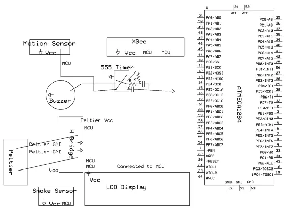
Source: Transform Your Home into a Smart Haven with DIY Wireless Automation
- What sensors does Smart Sitter use for motion, smoke, and temperature detection?
It uses a PIR motion sensor, an MQ-2 gas and smoke sensor, and an LM34 analog temperature sensor. - How are motion alerts signaled locally and remotely?
Motion triggers a 5V output from the PIR that actuates a 555-timer-driven buzzer locally and sends an alert via XBee to the user's computer, while the MCU displays ALERT! on the LCD. - How does the system provide climate control?
The MCU reads the LM34 temperature, receives a target temperature via XBee, and uses an H-bridge to set Peltier TEC current direction to heat or cool as needed. - What wireless method is used to communicate with the user's computer?
Wireless communication uses XBee modules operating under the 802.15.4 protocol connected to the MCU UART and the computer serial interface. - How does the system avoid false alert flickering on the LCD and UART?
Finite state machines and debouncing logic hold alert states until sensor outputs return low, preventing transient signals from causing rapid flicker. - What warm-up times are required for sensors?
The PIR sensor requires about 40 seconds to warm up and the MQ-2 smoke sensor requires about 48 hours of warm-up. - Which safety and coding standards are referenced?
The smoke detector complies with UL217 and UL268; the C code follows ANSI C standards; XBee use follows FCC regulations. - Can the system be extended to multiple remote devices?
Yes, XBee supports point-to-multipoint communication for additional interconnected units, though address management is required. - What open-source components were used in the project?
The Tiny Real Time multitasking kernel and the CoolTerm serial communication program were used under their open-source licenses.