Introduction
For our ECE 4760 final project, we designed, constructed, and tested a glove-operated system that dynamically simulates the classic toy, Etch A Sketch, on a TFT LCD screen.
In deciding what to build, our team wanted to create a device that would utilize several of the technologies overviewed in the course, in a fun, creative way. Introduced in 1960, the Etch A Sketch is an easily recognizable toy that anyone can enjoy interacting with, while showcasing some artistic ability. Our design achieves a user-friendly, low-cost simulation of this product, programmed onto a PIC32 microcontroller unit. Since our output is displayed onto an LCD screen, we also implemented multiple color modes.
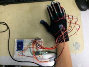
A photo of our completed project is shown below:
Since its invention, the Etch A Sketch has made its place in homes all over the world, and it is identified by all age groups. The toy has made its mark on film industry, with several appearances in the Toy Story trilogy. Furthermore, Etch A Sketch was inducted into the National Toy Hall of Fame in 1998 and has been listed as one of the 100 most memorable and creative toys of the 20th century. We decided it would be interesting to recreate it.
That being said, Etch A Sketch is a trademarked product, and we are in no way related to Etch A Sketch or related entities.
High Level Design
Overview
Our project incorporates a range of hardware and software design experience, including inter-chip communication, processing analog user inputs in real-time. A high level outline of our design is detailed in the following sections.
Logical Structure
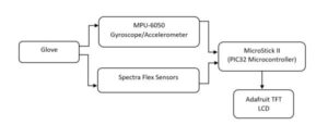
Data for our project is generated from the glove, which holds the five spectra flex sensors and the MPU-6050 gyroscope/accelerometer. The flex sensors act as variable resistors, whose resistances increase as the fingers are bent. Using a voltage divider, we pass an analog voltage reading into the MicroStick, which is converted to a digital value through the PIC32’s internal ADC. The MPU-6050 produces X-axis, Y-axis, and Z-axis outputs for acceleration and angular rates. These values are passed into the MicroStick via I2C communication protocol. The data from the glove’s components are then used to call draw functions to the LCD screen, allowing the user to see his or her inputs take form.
Hardware and Software Tradeoffs
During the design of our project, there were numerous tradeoffs we had to make for both hardware and software, among these, the type of display, communication protocol for the accelerometer, and the length of the flex sensors.
Our biggest tradeoff in this project was our choice of display. At the beginning of the project, we had to choose between using SPI communication to a TFT display, VGA to a LCD computer monitor, or an NTSC television. After some initial research, we found that VGA would be the most versatile, and effective method for displaying the outputs of our Digital “Etch A Sketch,” however, it was, by far the hardest to implement within software, and required the most processing power from the microprocessor. We ultimately decided upon implementing the display with the TFT, which was the easiest to implement in software, and had among the smallest processing requirements for the microprocessor. By using the TFT, we would be able to put more focus on the functional development of the Digital “Etch A Sketch” software, and be able to more easily debug the logical structure of that software.
In addition to the display, we had to make a decision on the communications protocol for the accelerometer. When choosing the accelerometer, we had the option of purchasing either the MPU 6050, or the MPU 6000. When looking at purchasing one, we realized that they functionally differed in only one area: the communications protocol used. The MPU 6050 utilized an I2C connection to the microprocessor, while the MPU 6000, used an SPI connection. Although the MPU 6000’s SPI connection would have been easier to implement, and just as functionally adequate, we chose to purchase the MPU 6050, and implement the more difficult, I2C protocol. This decision was due to the cost of the MPU 6000, and spending less on the accelerometer would allow us to use those funds for other areas of our project.
The last major tradeoff within our project involved purchasing the flex sensors. When looking to buy these, we had two main choices: 2.2” flex sensors and 4.5” flex sensors. While deciding between these two types of flex sensors, we realized that the 2.2” flex sensors, while half the price of the 4.5” ones, may not work as well for our application. On our glove, a 2.2” flex sensor would not cover the entirety of the each finger, and could lead to us not being able to differentiate a fully bent finger from a straight one. We ultimately decided to purchase the 2.2” flex sensors due to budgetary constraints and reconcile the potential for faulty finger readings within software.
Standards
To implement communication between the PIC32 and the variety of peripherals used, we utilized a variety of standards that have been developed, and open source communications libraries designed for these standards.
Communicating with the Adafruit TFT display was achieved using a Serial Peripheral Interface, or SPI. This consisted of a four wire interface, with SCLK, SS and MOSI outputs from the PIC32, and MISO output from the TFT display. The SCLK output from the PIC32 is the clock managing data transfer between devices, while the SS is the slave select which acts as a chip select input to the TFT display, governing when the TFT display should be reading data inputted over the other wires. The MOSI, or Master Output Slave Input, as well as the MISO, or Master Input, Slave Output, are the two wires over which data transfer actually takes place. To implement SPI for communication between the TFT display and PIC32, we used a library written for the PIC32 by Syed Tahmid Mahbub.
In order to communicate between our MPU6050 IMU and the PIC32, we had to utilize the I2C communication protocol. I2C is a standard developed by Phillips Semiconductor (the I2C name is now owned by NXT Semiconductor). This standard is typically used for communicating between lower speed integrated circuits (ICs), such as peripheral sensors, and faster ICs, such as microprocessors, and consists of two, bidirectional communication lines. The first of these lines, is SCL, or Serial Clock Line, transmits the clocking signal for the communication, while the other, SDA, or Serial Data Line, takes care of the data transmission between devices. In order to implement this protocol, we used and modified an open-source library developed by Jeff Rowberg.
Hardware
Flex Sensors
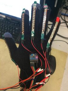
Our design used five Spectra Symbol Flex Sensors that allowed us to quantify how much each finger is bent. We attached a 2.2 inch flex sensor to each finger on the glove. Each flex sensor is a variable resistor – the resistance increases when each sensor is bent. We then constructed a voltage divider circuit for each flex sensor, whose outputs can then be sent to one of the PIC32’s analog-to-digital input pins.
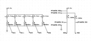
The voltage divider circuits were constructed to get a corresponding voltage from each flex sensor’s variable resistance. We found that for our flex sensors, there is a resistance of ~20 kOhm when fully flexed and ~10 kOhm when flat. To obtain a wide range of output values, we ended up using a 20 kOhm resistor as demonstrated in the diagram below:
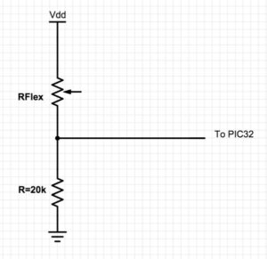
We used the following voltage divider equation: Vout = Vin * ( RFlex / (RFlex + 20k) )
We could then feed the outputs of the voltage divider circuits into the on-chip ADC of the PIC32. Finally, we soldered the connecting pins of each flex sensor to wire connectors and covered with electrical tape to make sure we did not accidentally break the flex sensor while bending.
MPU-6050 Gyroscope/Accelerometer
In order to detect the orientation and rotational movement of the user’s hand, we used a MPU-6050, which is a three-axis gyroscope and accelerometer. The MPU-6050 uses an I2C interface to communicate with the PIC32. I2C is designed to support multiple devices using a single dedicated data (SDA) bus and a single clock (SCL) bus which is used to send the accelerometer and gyroscope read data to the PIC32 when desired. By adhering to the I2C protocol, detailed later under the Software section, we can use the interface to regularly poll the MPU-6050.
TFT Display
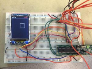
In order to display the user’s drawings, we decided to use a TFT display screen. We used the Adafruit TFT LCD Display Model 1480. In previous labs, we had already soldered on the TFT header and connected Vdd and ground to the display. In terms of the other pin connections, we used the following pin-outs:
TFT uses pins 4,5,6, 22 and 26 (RB0, RB1, RB2, MOSI1, SCLK1)
CK: connected to RB15 on the PIC
MOSI: connected to RB11 on the PIC
CS: connected to RB1 on the PIC
RST: connected to RB2 on the PIC
D/C: connected to RB0 on the PIC
VIN: connected to 3.3V supply
GND: connected to gnd
Glove
Our final product consisted of each flex sensor being individually sewn onto the fingers of our glove. The MPU-6050 was attached to the center of the back of the glove. Additional stitching was done to ensure that everything was secured to the glove and that the flex sensor readings were as accurate as possible.
The voltage divider circuit and all other additional circuitry was placed on a separate whiteboard, along with the PIC32 and TFT display. Extra wires were soldered onto the outputs of the gloves in order to provide a wider range of motion for the user.
Software
Flex Sensor Data
As mentioned earlier, the voltage divider inputs from the flex sensors are read into analog I/O ports and sent through the internal ADC to obtain digital values. Since the ADC can only handle one input at a time, each read cycle consists of five “set ADC channel” functions, with ADC reads following each. During each 120 millisecond cycle, the read functions store flex data into the same local variables, which are used to determine what hand gesture is being expressed.
Because flex sensor sensitivity varies between each component and finger motion ranges vary between fingers, we had to calibrate each flex sensor individually. This was done through an iterative process, where we read digital outputs for each finger, under each gesture, and selected appropriate cutoff ranges for “open” and “close.”
MPU-6050 Data
In order to determine hand orientation used for the finite state machine, we used a MPU6050 Accelerometer/Gyroscope. To communicate with this peripheral, we needed to establish an communication and data transfer through the I2C protocol. We found an excellent library, written by Jeff Rowberg, which helped us implement the communication. Using this library, we established communication, and collected data from the MPU6050 in a 3 step process. First, we used the command Setup_I2C(), which sets all the correct register addresses that will be used within the communication with the MPU6050. Then we repeatedly pinged the MPU6050 over the I2C connection with the commands Setup_MPU6050() and MPU6050_Test_I2C() until the MPU6050 sends back the expected information. Collecting the data from the MPU6050 is then easily done with the commands given in the library for getting the proper acceleration values.
Gesture Mapping
The user simulates the program by sending inputs through hand gestures. The key gestures for operation are “fist” versus “open hand” which determine whether or not the user is drawing or stopping. When stopped, the user has other gesture options, such as changing colors, clearing the screen, and finishing the program (all operations end). Each gesture has a specified function, as shown in the table below:
| Function | Gesture |
|---|---|
| Adjust draw angle | Rotate hand |
| Begin drawing | Fist |
| Stop drawing | Open hand |
| Once in color (stop drawing) mode, user can select colors: Red Green Blue White | Fingers form “1” Fingers form “2” Fingers form “3” Fingers form “4” |
| Clear screen | Thumb and pinky open, others closed |
| Done | Thumbs up |
Finite State Machine
The user simulates the program by sending inputs through hand gestures. The key gestures for operation are “fist” versus “open hand” which determine whether or not the user is drawing or stopping. When stopped, the user has other gesture options, such as changing colors, clearing the screen, and finishing the program (all operations end). Each gesture has a specified function, as shown in the table below:
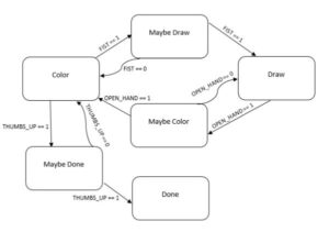
As shown, we implemented a debouncing mechanism by adding “Maybe” states. These states are used to avoid jitter between state transitions, since the PIC32 checks for transitions at a very fast rate. When entering either “Maybe Draw” or “Maybe Color” states, a 200 millisecond delay is initialized, after which the system checks for either an affirmation of transition (FIST==1 or OPEN_HAND==1) or a negation of transition (FIST==0 or OPEN_HAND==0). Similarly, the “Maybe Done” has a longer 1000 millisecond delay to avoid accidentally stopping the program before the user intends to finish.
We also utilized a similar FSM for color changing, which only occurs while the system is in Color mode. It contains states for the four colors (default at white), with an additional four “Maybe” states for debouncing. Debouncing happens as described above, except with a 400 millisecond delay, and the color returns to its previous state if the transition signal is not maintained over this period.
LCD Screen Output
The invisible cursor is initialized in the center of the TFT screen, within the draw space. Drawing, when enabled, occurs by spawning a small, 2-pixel radius circle every 120 milliseconds, while movement of the cursor happens concurrently at a rate of 2 pixels for each 120 millisecond cycle. The white border encloses the draw space. The cursor’s free movement is limited to within this box, and hitting a border results in movement along the inner wall, as directed.
Changing the draw direction is done by rotating the glove hand. Since human wrist rotation is limited to approximately 180 degrees, we mapped the 180 degrees of rotation to the 360 degrees of screen drawing. Pointing the back of the hand upwards results in drawing upwards, while pointing the back of the hand completely to left or right results in drawing downwards. Any hand angle in between completely left and completely right will give a corresponding left or right movement in the display, angled upwards or downward appropriately. Any angle outside the targeted 180 degree range – where the back of the hand is pointed towards the ground – will result in drawing downwards.
The following image shows an example TFT output:
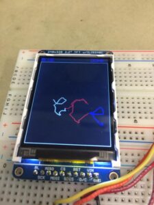
The above user has written “ece” in three different colors, then called the done signal. The top left corner shows the current draw color (BLUE), while the top right corner shows the current state (DONE). Other options for draw color are RED, GREEN, and WHITE, and the other states are DRAW and STOP.
Results
By the end of our project, we had created a fully functional glove-controlled drawing interface with all of the previously mentioned functions. The system is very responsive, and delays between gestures and on-screen outputs max out at 200 milliseconds, with the exception of the 1000ms delayed DONE signal. Assuming proper gesture control from the user, almost all intended gestures are registered, with a failure rate of less than 2%.
A video demonstration is available below:
Calibrations
In order to use our glove for the Digital “Etch A Sketch” we had to first calibrate the flex sensors, so that we could accurately determine if each finger was opened or closed. To do this, we fastened each flex sensor to the glove, and built the voltage divider for the flex sensors as was explained in the Hardware section. An image of the flex sensor orientation on the glove can be seen below:
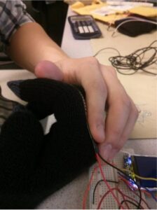
Once this was done, we read values off of the PIC32’s ADC for different position of the fingers. For each finger, we had an “open” value and a “closed” value read off the ADC. Because we wanted our device to be able to be used by many people, regardless of finger size, these values were separated by a “neutral” range, where we did not consider the finger open or closed. The values of these calibration data points can be seen in the table below:
| Close Threshold | Open Threshold | |
|---|---|---|
| Thumb | 125 | 130 |
| Pointer Finger | 360 | 400 |
| Middle Finger | 390 | 430 |
| Ring Finger | 385 | 400 |
| Pinky | 390 | 400 |
Accuracy/Controllability
After building and implementing our Digital “Etch A Sketch” game, we decided to do some tests on the accuracy, or “controllability” of the device. To do this, we told a user to draw a box, and gave him three tries to draw the box. We watched his progress as he learned to use the device and documented the images he created. Below is his first attempt:
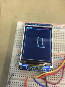
As you can see, the user’s first attempt at drawing the box was ultimately unsuccessful, and the resulting image looks very unlike a box. As he continued to use our device, however, his drawn images continued to improve. Below is his second attempt, and then a third attempt:
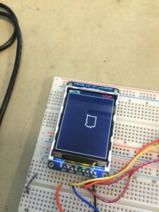
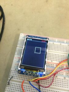
As is easily seen, the user’s second attempt was still reasonably unsuccessful, however his third image drawn looks to be fairly accurate. In this attempt, the four sides are almost entirely straight, and the corners are at near right angles.
Furthermore, while we noticed that the glove was not too difficult to pilot, we allowed some other individuals to try it out. We realized that by being designers of the glove, we were more comfortable with the functions and interface. The learning curve was steeper for outside users, as they did not know what to expect in terms of device sensitivity.
Usability
Our device was easily usable by all members of our group. We did notice in our testing, however, that the different hand sizes in our group did cause some trouble. This was easily fixed by making sure that the user’s hand was situated in the glove such that all, or almost all of their fingers were touching the end of the glove fingers. Once we made sure that this was the case, the glove worked even for our group members with smaller hands. Although it worked for us, our group is not representative of the entire population, so it may be a problem if a user’s hands are small enough.
In addition to the size of a user’s hands potentially causing problems with our implemented device, we may run into issues if the user is left-handed. Our glove is designed to be worn on the right hand, and therefore requires the user to be able to make all the gestures effectively with their right hand. Specifically, accurately turning the cursor requires sensitive movements, which could be difficult for less coordinated individuals. All of our group members are right handed and, as such, were very dexterous in the use of their right hand. If the user is left-handed, however, it may be more difficult for them to make some of the gestures, leading to problems using the device.
Attempts at Expanding Project Scope
While working on our project, we tried many things that didn’t work or were too ambitious. Originally, we wanted to make an interface that utilized the accelerometer readings to determine an accurate position within a “field of play” in which we would draw. This would allow us to accurately track the location of the user’s hand, and add an innovative feature to the original Etch A Sketch that we thought would make it easier and more fun to use. When originally starting out with this idea, however, we merely thought that we could obtain this position through integration from acceleration to position, and that this could be accomplished by approximating the integrals using Simpson’s Rule. This worked very poorly, as we soon found that the accelerometer is a very noisy device, and that the accuracy of a position estimation is quickly degraded by the integration of the measured acceleration error. Given more time to learn signal processing, we could try to tackle this using a technique such as a Kalman Filter, but this technique was beyond the scope of our knowledge during this class.
In addition to not being able to accurately estimate the position from the accelerometer measurements, we were originally going to attempt to display the output of the Digital “Etch A Sketch” on a VGA monitor. After working on this for some time though, we were unable to correctly communicate over VGA. We were able to accurately communicate horizontal and vertical sync signals required for communication, but unable to time our video data transfer. Given additional time, we think this would be a good continuation of the project.
Conclusions
Our results met our expectations, as we successfully developed all of the functions we were aiming to program. Failure rates were also very acceptable.
Looking towards the future, some additional functionality for implementation include the ability to move the cursor without drawing and the ability to output onto a more standard display, such as VGA. The former would allow the user more flexibility in draw designs, since they would essentially be able to “pick up their paintbrush.” The latter design would allow the user to draw on a larger screen, such as a computer monitor, which would be more enjoyable than drawing on our 2.2” LCD screen.
In terms of play modes, we can add a training game mode, which would automatically draw shapes onto the screen, which the user would have to copy over as accurately as possible. This mode can be scored by both completion speed and copy accuracy, allowing users to compete for the highest score while simultaneously practicing their drawing skills.
Relevant Standards
Communication with peripheral devices was easily accomplished and implemented according to various standards. As mentioned in the High Level Design section, we used SPI to communicate with the TFT LCD display. This was done using Syed Tahmid Mahbub’s library for PIC32, which can be found, with explanations, in the References section. In addition, we used the I2C protocol to communicate with the MPU6050 IMU, and implemented this using Jeff Rowberg’s library which can also be found in the References section.
Ethical Considerations
While designing and building our project, we made sure to comply with the IEEE Code of Ethics, by designing our project in a safe and responsible manner. We made sure to look into all of the possible safety concerns of the project, and kept the user’s safety at the forefront of our design. All of our claims about the project are realistic and wholly based on collected data. In addition, we have included and cited all material not created by us in this report. We also shared tables in our lab workspace, so we made sure to safely store all components in their correct locations and maintain a clean and safe working environment.
Legal Considerations and Intellectual Property
For our project, there are very few safety concerns that need to be considered. The biggest safety issue we need to consider are the live wires within the gloves. If the gloves malfunction and a short occurs with direct contact with the skin, a slight electrical shock could occur. Other safety issues to be considered will be the wires from the gloves to the pic32. If the user is not careful, he or she could become entangled in the wire and injury could occur.
As mentioned before, we used to open source libraries for this project. One was for SPI communication between the PIC32 and the TFT display, and was written by Syed Tahmid Mahbub. The other was for the I2C communication with the MPU6050, and was created by Jeff Rowberg. Our use of these libraries was legal, and completely within legal use.
Our code was based off of code developed by Bruce Land and Syed Tahmid Mahbub for Cornell University’s ECE 4760 class. Apart from this code and the open source libraries mentioned above, we wrote all of our own code based off of a variety of examples in the public domain. Our project is based off of a patented children’s toy, the Etch A Sketch (a trademarked name), and therefore, we do not have any patent or commercial opportunities for our project.
Schematics
The following schematic shows circuitry used for flex sensors and MPU-6050 operation, where the bottom connections are PIC32 analog/digital inputs:
Source: Digital “Etch A Sketch” Glove
