Summary of PIC16f628 DS18B20 Adjustable thermometer circuit
Summary (under 100 words): A DIY thermostat using a DS18B20 temperature sensor, PIC16F628 MCU, and a 3-digit 7-segment display provides 0–99.9°C reading with 0.1°C resolution. User-set target temperature and a configurable hysteresis tolerance (0.0–5.0°C) prevent rapid relay cycling. Settings are saved to nonvolatile memory. Controls: Set, Up, Down buttons for adjusting target and tolerance. Project files include Proteus schematics, PCB, and PICBASIC source.
Parts used in the DS18B20 Adjustable Thermometer Circuit:
- DS18B20 temperature sensor
- PIC16F628 microcontroller
- 3-digit 7-segment display
- Relay (for heater/boiler control)
- Set button
- Up button
- Down button
- Nonvolatile memory within PIC (EEPROM)
- Multiplexing active elements/drivers for display
- Proteus ARES/ISIS compatible PCB components (connectors, traces, decoupling capacitors)
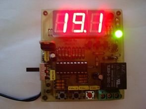
A friend of mine and I want to share with you what I did to set the thermostat circuit. As I used the circuit temperature sensor Ds18B20. 3-digit, 7 shows the screen with dijit. Please note that the range of 0 to 99.9. When the relay circuit arranged to set value is designed to get to the bottom of the page. Set the value of 0.1 degree sensibility. Very suitable for the use of the electric heater or boiler.
 In addition to the circuit and have the tolerance setting, maybe the temperature set below the value of the operation of the relay as soon as I added something like this to disallow. The lower limit of temperature. If it weren’t for the tolerance setting, the heater is activated and disabled too often (etc) to increase energy consumption and to relay quickly melt may cause.
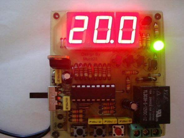
I’m going to wait until the temperature value from falling after the relay runs. After the temperature reaches the set value, the relay is switched off. can be set to between 0 and 5 degrees of 0.1 degree precision.
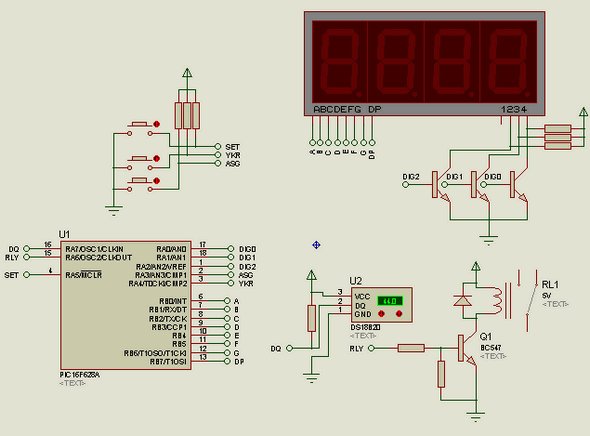
All values are saved in the memory. They are retained in the memory of electricity will not be deleted. The circuit works as mutiplex. I mean, at least I made the circuit with active elements.
Set the setting is as follows:
Press the Set button while the main work of the disabled. After a brief set of post appears on the screen, set the value to the screen. The House temperature after the comma starts blinking. Use the up and down buttons the temperature is adjusted. If you hold down the up and down buttons you can switch quickly to a certain period of time.
After pressing the Set value adjustment set the next setting of the tolerance setting. In the same way there is a value in degrees between 0 and 5.0. This tolerance setting. Here we enter the value until the temperature is expected to drop. Return to the main menu after pressing the tuning work.
Circuit of the Proteus ares isis pcb diagram and source code files PicBasic: pic16f628-ds18b20-adjustable-thermometer-circuit.ZIP
Alternative File Download LINK list (in TXT format): LINKS-14126.zip
- What temperature range and resolution does the circuit display?
The display shows 0 to 99.9 with 0.1 degree resolution. - How is relay chatter prevented?
By setting a tolerance (hysteresis) between 0.0 and 5.0 degrees so the relay only switches after temperature falls past the set lower limit. - How are target temperature and tolerance adjusted?
Press Set while idle, then use Up and Down to adjust the target; press Set again to adjust tolerance similarly. - Are settings retained after power loss?
Yes, all values are saved in nonvolatile memory and remain after power loss. - What controls are used for fast adjustment?
Holding the Up or Down buttons allows rapid change of values. - Which microcontroller and sensor are used in the project?
The project uses a PIC16F628 microcontroller and a DS18B20 temperature sensor. - What files are provided with the project?
Proteus ARES/ISIS schematic, PCB diagram, and PICBASIC source code ZIP file are provided. - What is the intended application for this thermostat circuit?
It is suitable for controlling electric heaters or boilers.