Summary of Digital Watt meter using PIC16F876
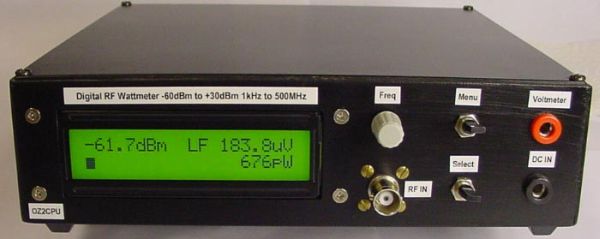
This article describes a digital wattmeter featured in Elektor Magazine (October 2002), designed around the PIC16F876 microcontroller. It measures RF power from -60 to +30dBm across a wide frequency range, utilizing an AD8307 detector and EEPROM for calibration data storage. The device features a POWERTIP LCD display with adjustable backlighting and supports battery operation with specific resistor modifications.
Parts used in the Digital Wattmeter:
- PIC16F876 microcontroller
- AD8307 signal detector
- POWERTIP 20-character 2-line LCD display with LED backlight
- EEPROM memory chip
- PCB (Printed Circuit Board)
- Input attenuator components
- Variable capacitor for input circuit adjustment
- R30, R26, and R27 resistors
Updated 3. Sep. 2002.
If you are from Denmark ! read the Danish version !!
In the good old days I had some parts but now
This Wattmeter is in ELEKTOR MAGAZINE OKTOBER 2002, they will sell PIC and PCB
The extra input B is for a later SWR brigde project, also the TX serial output will be in use later.
The uncalibrated signal response is: +1/-1 dB from 1MHz to 450MHz.
Input SWR vill varry from 1.00 to 1.30, depending on input frequency.
To make the SWR this good, you need to assemble the input circuit correct and adjust the capasitor.
Input power range: -60 to +30dBm that is 1 nW to 1 Watt.
This instrument can be used and calibrated from 1 kHz and up to 500 MHz
It is possible to measure power relative all the way up to 900Mhz
A software routine can calibrate the 0dBm point at 5 different frequencies to make this instrument accurate within 0.5dBm !!
The calibration data is stored in EEPROM so the instrument will remember all, also without power.
At frequencies above 300Mhz this instrument should not exceed inputs over +20dBm (100mW) to keep the good accuacy
This is a documented weekness in the AD8307, this is not a big problem, if you are aware of this, then it’s just a matter of using the right input attenuator
If battery opperation: do not connect R30, also change R26 and R27 to 4k7
Ideas taken from articles in: QST June 2001 page 38 and Funkamateur 12/99 page 1383 And Elektor 1/99 page 26
The display, shows dBm from -60 to +30dBm, RF Voltage and RF Power and Bargraph in 1db step.
The backlite is verry powerfull, I had to change R30 to 10E
Also I must complement the POWERTIP display for it’s exelent contrast and viewing angle and low prize !
I use a POWERTIP display with 20 caracters in 2 lines with LED light.
Powersupply current is:
With no light: = 30 mA. (R30 = NC)
Normal light: = 120 mA. (R30 = 10E)
Power light: = 200 mA. (R30 = 4E7)
For more detail: Digital Watt meter using PIC16F876
- What is the measurable power range of this instrument?
The instrument measures input power ranging from -60 to +30dBm, which equals 1 nW to 1 Watt. - How does the calibration process work for accuracy?
A software routine can calibrate the 0dBm point at five different frequencies to ensure accuracy within 0.5dBm. - Where is the calibration data stored?
The calibration data is saved in EEPROM so the instrument retains settings even without power. - What limits the input power at high frequencies?
Above 300MHz, inputs should not exceed +20dBm to maintain good accuracy due to a weakness in the AD8307. - How can I modify the circuit for battery operation?
For battery use, do not connect R30 and change R26 and R27 to 4k7 resistors. - What are the current consumption levels with different lighting settings?
Current draw is 30 mA with no light, 120 mA with normal light, and 200 mA with power light enabled. - Does the device measure relative power up to 900MHz?
Yes, it is possible to measure power relative all the way up to 900MHz. - What is the uncalibrated signal response frequency range?
The uncalibrated signal response is +1/-1 dB from 1MHz to 450MHz.