Summary of Unipolar Stepper Motor Control Circuit with PIC16F877
This article describes a unipolar stepper motor control circuit using a PIC16F877 microcontroller with buttons to set steps, direction, and speed, supporting 1 to 200 steps and speeds from 1 step/sec up to over 200 steps/sec. The design uses ULN2803 Darlington drivers, allows menu navigation via arrow keys for settings and zeroing, and limits winding current to 500 mA. Proteus ISIS simulation and PicBasic Pro source files are provided in the downloadable ZIP.
Parts used in the Unipolar Stepper Motor Control Circuit with PIC16F877:
- PIC16F877 microcontroller
- Unipolar stepper motor
- ULN2803 Darlington transistor array
- Push buttons (arrow keys and menu/select)
- Power supply capable of supplying motor currents up to 500 mA per winding
- Supporting passive components (resistors, capacitors for MCU and input debouncing)
- PCB or breadboard and wiring
- Proteus ISIS simulation files (project file)
- PicBasic Pro source code files
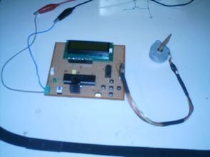
Hello friends, this article, unipolar stepper motor control circuit related work.
The purpose of this circuit is connected to unpolar stepper motor I designed buttons,
select the number of steps we determined the direction, speed, and with it a system that implements the step motor commands. Pic16f877 microcontroller circuit.
 When first working circuit stepper motor 120 degree back and forth by applying signal makes zero adjustment. Located on the circuit using the arrow keys to switch between menus and menu you can adjust the volume. The engine speed setting step / sec are denominated in more than 200 steps / sec and at least 1adım/sani of moving at the speed .motor horse could step count up to 200 steps and at least one step atabilir.devre maximum of an engine winding 500 mA current passed.
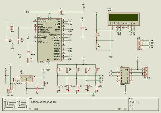 As motor drive uln2803 darlington transistor integrated connection is selected.
Unipolar stepper motor control with PIC16F877 project belongs to isis proteus simulation file PicBasic Pro code files: unipolar-stepper-motor-control-circuit-with-pic16f877.ZIP
For more detail: Unipolar Stepper Motor Control Circuit with PIC16F877
- What microcontroller is used in this project?
The project uses a PIC16F877 microcontroller. - How many steps per second can the system set?
The engine speed setting covers from at least 1 step/sec up to more than 200 steps/sec. - What is the maximum current allowed through a motor winding?
The circuit allows a maximum of 500 mA through a motor winding. - Which driver IC is used to drive the motor?
The ULN2803 Darlington transistor array is used as the motor driver. - How are settings like steps, direction, and speed selected?
Buttons including arrow keys on the circuit are used to switch between menus and adjust settings such as steps, direction, and speed. - What software files are provided with the project?
The project includes Proteus ISIS simulation files and PicBasic Pro code files in a ZIP archive. - Does the circuit provide a zero adjustment or homing function?
Yes, applying a signal causes the stepper to move back and forth by 120 degrees for zero adjustment. - How many steps can be counted or selected in the motor step count?
The motor step count can be set up to 200 steps and at least one step.