Summary of Build a musical EKG with the Freescale FRDM-KL05
Summary (under 100 words): The author built a wearable ECG-based alert system using a Freescale FRDM-KL05Z board and an Olimex EKG/EMG shield. The microcontroller samples ECG, detects R-wave anomalies, and sends control pulses to a modified voice-changer audio module to alter music pitch when irregularities occur, allowing passive continuous heart monitoring. Development used Keil uVision and Freescale example code and support.
Parts used in the Musical EKG:
- Freescale FRDM-KL05Z development kit (MKL05Z32VFM4)
- Olimex Shield-EKG/EMG module
- Electrode set compatible with the EKG shield
- Voice changer audio processing kit (modified for line-in/line-out)
- Audio line-in and audio line-out connectors
- Wires for TTL control to high pitch and low pitch switches
- Diodes for level isolation between 3.3V MCU and 5V voice changer
- Soldered Arduino-type headers on FRDM-KL05Z
- Keil uVision development environment (software)
Short Introduction:
I have been following the Battle of the DreamBoards Championship with interest and I enjoyed the variation of functionality features put together in each of the dreamboards. I especially had my attention attracted by the combination of audio inputs and outputs, analog to digital and digital to analog converters, and the microcontroller digital processing of signals that I saw in PC64, which was also the winning dreamboard. This combination of features inspired me to build one of the old ideas that has been waiting “dormant” somewhere in my mind for a while. Here is a description of my project:
Why I built this project:
Electrocardiographs (ECG) measure electric signals generated by the heart and display them in a graphical format on a screen or on a hard copy electrocardiogram. Most of the times when I go to a doctor for check-up I have one of these electrocardiograms measured on my heart. More extensive monitoring of the heart activities uses 24 hours ECG or even two weeks ECG. The recorded data is then processed in medical offices to determine if there was any ECG waveform aberration. So in my case once in a while I may have an irregular heart beat or a premature ventricular contraction (PVC) which typically happen in normal heart activity but if there are too many then they need medical attention.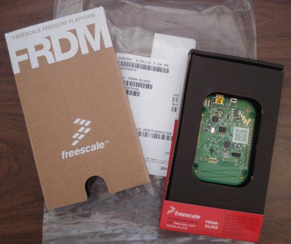
What am I trying to do:
ECG measurement and analysis is a powerful tool for detecting problems with the heart activity when it is recorded, but how about the rest of the time? Can I have a device that continuously monitors the heart activity every day through ECG measurements? The technology is available and ECG heart monitors are inexpensive, but the problem I see is how I can actually use them to continuously monitor my heart activity? For how long I can keep my eyes on the screen and watch the ECG waveform in real-time? I also need to do other things during the day so I am not able to continuously watch that screen. If I record the ECG data for a period of time I will then need to go and analyze it, which takes time and thus I find inconvenient.
I kept thinking about how I could monitor my heart activity without disturbing my normal activities. So I decided to build an ECG device that can be attached to an audio system and when it detects aberrations in ECG waveform it distorts the music or voice that plays through the audio system (CD player, radio, TV, or any appliance that outputs an audio signal). This way I can monitor my heart activity while doing my regular daily activities without spending specific time to watch or analyze he recorded the ECG waveforms.
How does it work:
The ECG unit continuously measures the ECG and when it detects an aberration in heart activity it sends a command to the audio unit which then either increases the pitch of the music or voice played by the speaker.
How I implemented it:
I have chosen to implement this project on a Freescale FRDM-KL05Z development kit that has a MKL05Z32VFM4 microcontroller This is a very inexpensive microcontroller and development kit that can operate up to 48MHz has 32kB of flash non volatile memory various analog and digital peripherals and what I planned to use in my application it has a 12-bit analog-to-digital converter This development kit supports the open standard embedded serial and debug adapter OpenSDA What I also liked on this FRDM-KL05Z development kit was that it has Arduino type GPIO headers that allows me to easily connect Arduino type shield modules Thus I could use a shield module for the front end ECG analog path
Here is a picture of the Freescale FRDM-KL05Z development kit
Setting up the design environment for the Freescale FRDM-KL05Z board
The first step after I received the board was to setup the design environment In this process I found very useful a quick start guide file FRDM-KL05Z Quick Start Guide(Rev 1.1 available to download on the Freescale website part of a quick start package with precompiled examples and OpenSDA applications
This document has guided me step by step through installing the required drivers, the OpenSDA programming and debug environment, and loading and running an application. I found it quite convenient the MSD flash programmer where I only need to drag and drop the file and it gets automatically programmed into the microcontroller.
After getting the FRDM-KL05Z board up and running I installed Keil micro vision(uvision programming environment This tool provides source code editing and program debugging so I have chosen to use this platform for the rest of my work on this project
I also want to mention that during this setup process I bumped into various issues for which I either found solutions on the Freescale support webpage or I got help from the Freescale support team. I was impressed on how fast the support engineers responded to my requests, for example, I sent a request on July 6 at 9 PM and a support representative responded to me in 5 hours, at 2 AM. I also contacted the support team on a Saturday with a design question about configuring GPIO pins, and I was surprised to get an answer during that weekend on Sunday; I thought I will need to wait until the week started, but the response came during that weekend.
The Electrocardiogram Circuit:
For the front end analog amplification of heart electrical signals I chose to use an Olimex Shield-EKG/EMG module from Newark store.
This ECG shield works with multiple types of electrodes, and I chose this set, also from Newark store, that attaches to the shield module through a connector:
The ECG shield board connectors plug directly into the headers that I soldered on the Freescale FRDM-KL05Z board
Before I describe the rest of the components of this project I would like to show a block diagram.
Block Diagram of the Entire System
This system has three main parts ECG front end module FRDM-KL05Z data processing and an audio processing module
The ECG shield module measures continuously the ECG waveform which is then sampled by the analog to digital converter inside the development kit The sampled values are processed to extract the peak R-waves and store the samples of a R-wave to R-wave cycle which represent the time between two consecutive heart beats These samples become the expected values for the following cycle So in each R-wave triggered cycle the FRDM-KL05Z code compares the real time measured ECG samples with the expected values and if it finds discrepancies it generates specific flags When a flag is detected the code generates control signals that are sent to the audio processing module to either increase or decrease the pitch of the audio signal that passes through the module For example if the person monitored by this system listens to music on the radio CD or mp3 player the music will change the pitch higher or lower depending on what aberration has been detected on the ECG waveform Similar sound pitch changes happen if the person watches a show on the TV or DVD player This way the heart activity is monitored while doing other activities without the need to spend dedicated time for this monitoring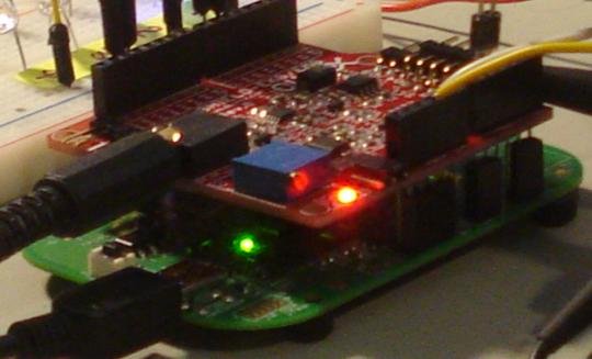
Schematic of the System
The main unit is the evaluation kit which provides power to the ECG shield and provides the control signals to the audio processing board The ECG shield amplifies and filters the electrode signals and then sends the output to PTB13 GPIO port of the MKL05Z32VFM4 microcontroller on the FRDM-KL05Z board This microcontroller analyzes the analog ECG waveform and when it detects heart activity problems it sends two digital pulse signals to the audio processing module one that increases the pitch and one that decreases it The microcontroller also controls four LEDs that display what was wrong with the ECG waveform that generated a flag The four ECG aberrations signaled are LED1 Early R-wave peak(Irregular heart rate too short LED2 late R-wave(Irregular heart rate too long LED3=P-wave and/or T-wave magnitude too large LED4=P-wave and/or T-wave magnitude too small
The audio processing module is a voice changer kit available to purchase from various places, like for example on amazon.com:
http://www.amazon.com/Velleman-MK171-Voice-Changer/dp/B004XZQ6RE/ref=sr_1_13?ie=UTF8&qid=1440257874&sr=8-13&keywords=voice+changer
Here is a picture of my audio processing board:
I have modified this kit by adding an audio line-in and an audio line-out connectors instead of soldering a microphone and a speaker to the board.
In order to control this kit with TTL pulses instead of pressing the buttons I had to solder two wires on the high pitch and low pitch switches and one on the ground These signals are normally pulled-up and they need to be driven low to get the same effect as pressing the buttons but because board operates at 3.3V and the voice changer kit at 5V I couldn’t connect directly these wires to the outputs To solve this issue without adding level shifters I inserted a diode in series with the wire The diode allows pulling down the node but blocks the 5V coming into FRDM-KL05Z when the signal is not asserted
Developing the Code
I started from two example codes and I expanded them into the complete code. One of the example code was LED_Blink that comes in the KL05-SC package that I downloaded from Freescale website. There is a guide document in this package that describes how to install and run the code examples, FRDM_KL05ZSCG_KEIL_rev1, which I found very informative and easy to follow. This one is specific for Keil tools, and there are two other similar documents for IAR and Code Warrior tools.
So I used the LED_Blink to learn how to generate and send digital signals to output ports, which I needed for controlling the audio processing module.
The other example code that I used was AdcDemoWithDMA This code configures calibrates and performs analog-to-digital conversions using the 12-bit ADC inside the MKL05Z32VFM4 microcontroller I found this example code very useful for implementing my ECG signal sampling function and I decided to actually start form this example code and build the rest of the project on top of it
For more detail: Build a musical EKG with the Freescale FRDM-KL05
- What microcontroller board was used?
The Freescale FRDM-KL05Z development kit with MKL05Z32VFM4 microcontroller was used. - What analog front end was used for ECG signals?
An Olimex Shield-EKG/EMG module was used as the ECG front end. - How does the system notify when an ECG aberration is detected?
The microcontroller sends control pulses to an audio processing module which alters the pitch of played audio. - How are ECG signals sampled?
The MKL05Z32VFM4 12-bit ADC samples the ECG shield output. - How were the voice changer buttons controlled digitally?
Wires were soldered to the high pitch and low pitch switches and driven by TTL pulses through diodes for level isolation. - Why were diodes inserted between the MCU and voice changer?
Diodes allowed pulling the 5V kit inputs low without exposing the 3.3V MCU to 5V when not asserted, avoiding level shifters. - Which example codes were used to start development?
LED_Blink was used to learn GPIO output control and AdcDemoWithDMA was used for ADC sampling with DMA. - What development environment was used for coding and debugging?
Keil uVision was used for source code editing and debugging. - What ECG aberrations are indicated by the four LEDs?
LED1: early R-wave (too short interval); LED2: late R-wave (too long interval); LED3: P-wave or T-wave magnitude too large; LED4: P-wave or T-wave magnitude too small.