Summary of Innovative Robotics: A Comprehensive Project Exploration
Summary: This project designs a glove-controlled robotic pick-and-place arm using flex sensors, PSoC and PIC microcontrollers, and DC/servo motors. Flex sensors convert finger bends to voltages via voltage dividers; PSoC ADCs digitize signals and UARTs transmit data. PIC microcontrollers (PIC16F877A/PIC18F452) drive stepper/DC motors through L293D and control servos for five-axis arm motion. The system enables remote PC control, sensor-based autonomy, and precise manipulation for industrial-style pick-and-place tasks.
Parts used in the Glove-Controlled Robotic Arm Project:
- Flex sensors (bi-directional, approx 10K flat, 30–40K at 90°)
- Copper foil laminate (for flex sensor construction)
- Acetate substrate (for flex sensor)
- Heat shrink tubing
- Resistive conductive material (carbon-loaded polyethylene strips)
- Voltage divider components (resistors, wiring)
- PSoC microcontroller (PSoC 1 family, M8C core)
- Delta-Sigma ADC (DelSig) within PSoC
- UART interface (on PSoC)
- PIC microcontrollers (PIC16F877A and PIC18F452 / PIC16F628A references)
- L293D motor driver IC
- Stepper motor (for aligning robot arm movement)
- DC motors (series/shunt/compound type discussion; used for actuation)
- Servo motors (RC servos with control, power, ground wires)
- ATmega16 (mentioned as single microcontroller in one arm variant)
- Gripper mechanism (servo-actuated)
- Castor wheels (for base rotation without gears/bearings)
- USB hardware (for PC GUI interface)
- Power supply (5V/12V SMPS example: 5V-25A, 12V-5A)
- 32-channel universal servo controller board (for multi-servo control)
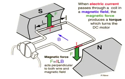
A DC motor functions as an electromechanical device, translating electrical signals into mechanical movements. The rotation of the motor correlates directly with the applied input pulses, with the sequence of pulses determining the direction of the motor shaft’s rotation. The speed of rotation is directly linked to the frequency of input pulses, while the length of rotation corresponds to the number of input pulses applied. DC motors are advantageous for applications requiring controlled movement, allowing precision in rotation angle, speed, position, and synchronism.
The project’s objective is to develop a robot arm that moves in alignment with the stepper’s rotation, finding utility in various applications. The project facilitates DC motor control using a glove interpreter. A glove, serving as a hand covering, incorporates flex sensors that detect hand movements. Flex sensors alter their resistance based on the degree of bend, converting this change into electrical resistance. The resistance value is then converted into a voltage value using a voltage divider.
The project employs a microcontroller unit (MCU) based on the PSoC architecture, specifically the PSoC Creator. This MCU integrates analog and digital peripheral functions along with an Analog-to-Digital Converter (ADC) and Universal Asynchronous Receiver-Transmitter (+UART). The Delta Sigma ADC/DelSig is used for precision measurements, offering low-power, low-noise characteristics. The +UART provides asynchronous communications and can be configured for various modes, such as full duplex, half duplex, receive-only, or transmit-only versions.
The ADC/DelSig operates in continuous mode for audio processing and various multi-sample modes for scanning multiple sensors. The +UART supports multiple configurations, allowing flexibility in baud rate, parity, data bits, and stop bits. The analog signal is digitized within the PSoC MCU, and the output is serially transmitted to the main #C (microcontroller).
*Microchip Technology has developed widely-used processors known as PIC microcontrollers, featuring integrated peripherals, memory, an internal bus, and versatile applications. Initially denoted as “Programmable Intelligent Computer,” PIC is now commonly recognized as a “Peripheral Interface Controller.” This project specifically involves the microcontroller PIC16F877A, programmed to manage the stepper motor drive. The PIC16F877A coordinates with the L293D IC, controlling the rotation of the stepper motor, subsequently generating the corresponding movements on the robot arm.
1.2 OBJECTIVE
A robot is a machine capable of performing tasks independently, following programmed instructions from humans. The inaugural robot, named Electro, and his canine companion, Sparko, made their debut at the 1939 New York World’s Fair. While connected, Electro could articulate around 700 words and move both backward and forward.
In the 1920s, Karel Čapek from Czechoslovakia introduced the term “robot” on stage. Our project aims to design and implement a scaled model of a pick-and-place robot, capable of picking up and placing objects in various locations. This project was chosen due to the widespread use of such machines in various industries like car manufacturing, shipyards, and assembly lines.
Microprocessors and microcontrollers play a vital role in embedded system products. Embedded systems are dedicated to a specific purpose and remain unchanged throughout their lifespan. These systems utilize microcontrollers to perform a singular task. Automation, characterized by the application of control systems and information technologies, aims to minimize the reliance on human labor in the production of goods and services.
AutoMotion, established in 2005, initially operated as a distributor of conveyors and conveyor accessories. In the realm of industrial automation, it represents a leap beyond mechanization. While mechanization provided machinery to assist human operators with physical tasks, automation significantly reduces the necessity for human sensory and mental input.
SCOPE OF THE WORK
The robotic system’s mechanics rely on actuators, specialized devices that activate mechanical components through a sensor link, particularly those connected to a computer. The robotic arm is designed for swift, precise, and repeatable movements. It incorporates features such as base rotation, shoulder, elbow, and wrist motion, along with a functional gripper that allows for five independent axes of movement. Small and lightweight grippers are integrated to grasp objects, while a mobile base enables the robot’s free movement. Flight sensors are incorporated to identify objects and their colors.
The electronic control is facilitated by a microcontroller, programmed with predefined instructions to issue simple positioning commands for movement. Intelligent control software, developed using a high-level graphical programming language like Visual Basic, operates the microcontroller and provides control pulses to the servos. Notably, commands can also be issued from an external source, such as a PC, emphasizing the intention to design user-friendly software for this purpose. The entire robot is under the command of the microcontroller, and remote operation by an individual from a distance of ten to fifteen meters is achievable. All these functionalities are based on microprocessor technology, allowing the integration of a complete CMC (Central Processing Unit, Memory, and Communication) on a single chip.
The communication between the microcontroller and the FPG-based module utilizes the FPG-module, ensuring secure communications. The chosen microcontroller is the PIC16F628A, featuring a Harvard architecture. Microprocessors and microcontrollers, prevalent in embedded system products, find extensive use in systems dedicated to a single purpose, demonstrating stability throughout their lifecycle. This project presents a comprehensive solution for the control of a robotic system.
2.1. SYSTEM OVERVIEW
The emergence of high-speed technology, coupled with increased computer capacity, has opened up realistic possibilities for innovative robot controls and the implementation of novel control theory methods. This technological advancement, driven by the demand for high-performance robots, has led to the development of faster, more accurate, and intelligent robotic systems. These advancements utilize new control devices, sophisticated drives, and advanced control algorithms.
This project introduces an economical solution for robot control systems, offering versatility for various sophisticated robot applications. The control system comprises a glove, a microcontroller module, and a main microcontroller responsible for gathering data from the microcontroller module and orchestrating the control of the robot.
2.1.1. PREVIOUS WORKS
Our robotic implementation is an amalgamation of distinct robot designs. The Axis Arm, initially designed for simulating the Towers of Hanoi game, has three axes and was previously employed for industrial applications, particularly for pick-and-place operations. A stationary pick-and-place robot was specifically developed for handling stationary objects, while a telephone-operated pick-and-place robot was designed for managing telephone calls.
The entire robotic system is governed by a microcontroller, and commands from a PC are received by the microcontroller, allowing remote operation by an individual situated approximately ten to fifteen meters away. These robotic functionalities are all rooted in microprocessor technology, which empowers manufacturers to integrate an entire central processing unit (CPU) onto a single chip.
Communication between the microcontroller and the personal computer involves the transmission of commands, providing a secure communication interface for seamless operation.
2.1.2. PROPOSED WORKS
Our enhancement to the existing robotic arm includes the integration of a versatile set of sensors aimed at providing it with autonomous mobility. These sensors play a crucial role in enabling the arm to identify its surroundings, detect obstacles, and consequently move freely in response to user commands, whether issued through the microcontroller or a manual computer interface. The microcontroller orchestrates the necessary commands, allowing the robot to navigate, identify colors of specified objects, grasp those objects, and execute the required tasks utilizing its five-axis arm capability.
Comprising five main components – the brain, typically a microcontroller module, actuators, and mechanical parts such as motors, pistons, grippers, wheels, and gears – the robot exhibits a range of movements, including base rotation, shoulder, elbow, and wrist motion. No soldering is required for the electronics, and aside from basic construction supplies, all components necessary for assembling a functional robot are included.
While a microcontroller is essential for issuing simple positioning commands, the robot’s capabilities extend to practical tasks, exemplified by its potential to prepare a cup of tea. In this scenario, the robot can autonomously move, grasp a spoon, measure a specified quantity of sugar, and deposit it into a cup.
Despite its advantages, the robot faces certain drawbacks. The servomotor, due to its high cost stemming from limited demand and the expense of rare earth magnets, stands out as a significant limitation. Additionally, controlling the speed of a servomotor is more complex compared to a DC motor. Unlike a DC motor, where speed is easily regulated by adjusting the applied DC voltage, this complexity poses challenges. Future advancements in technology may address these drawbacks, paving the way for more efficient solutions. Notably, the DC motor boasts resilience against mechanical overload, providing high output power relative to its size and weight.
2.1.3. FUTURE WORKS
3. BLOCK DIAGRAM
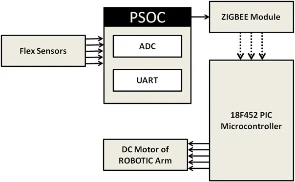
4. BLOCK DIAGRAM EXPLANATION
4.1 FLEX SENSORS
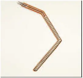
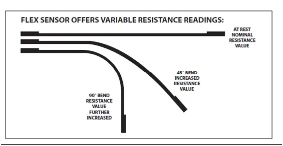
Flex sensors represent passive resistive components designed for detecting bending or flexing. These sensors exhibit a decrease in resistance proportionate to the degree of bending in either direction. The sensor under consideration has dimensions of approximately 3/8″ in width and 5″ in length, but adjustments can be made to increase width and length based on specific application requirements.
Functioning as analog resistors, flex sensors operate as variable analog voltage dividers. Carbon resistive elements within a thin, flexible substrate are present in the sensor. The quantity of carbon directly correlates with the resistance, where more carbon results in less resistance. When the substrate is bent, the sensor produces a resistance output corresponding to the bend radius. For a standard flex sensor, a 0-degree flex yields a 10K resistance, while a 90-degree flex produces resistance in the range of 30-40K ohms. The Bend Sensor, on the other hand, indicates resistance within the range of 30-250K ohms.
4.1.1 COMPONENTS
Figure 1 illustrates the components required for crafting the bi-directional flex sensor, with details provided below. It is important to note that the dimensions mentioned here are specific to the sensor outlined in this article and can be adjusted for sensors of larger widths and lengths.
1. Copper foil laminate: 1/4″ x 4.5″
2. Acetate: 1/4″ x 4.5″ x .010 thick
3. Heat shrink tubing: 3/8″ dia x 5″
4. Resistive material: 5/16″ x 5″
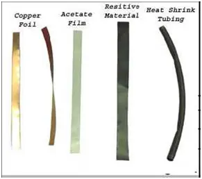
In the electronics industry, flexible circuits are created using copper foil laminate, a thin layer of copper cladding on a plastic substrate like acetate. The material being utilized in this context is single-sided copper, with copper on one side and plastic substrate on the other. The copper cladding is cut into two pieces, each measuring 1/4″ in width and 4.5″ in length. The material is easily cut using scissors. To each strip’s one end, approximately 6″ of wire is soldered. To facilitate soldering, it may be helpful to tin the bottom 3/8″ of each strip. The wires are then soldered to one corner side of each strip. The choice of which side to solder does not matter, but it is crucial to ensure that both strips are soldered on the same side.
4.1.2 RESISTIVE MATERIALS
Various resistive materials, including cloth, plastic, and paper, are readily available. The common characteristic among these materials is that they possess some degree of conductivity or resistance. The level of resistivity in the material plays a crucial role in determining the operational scale of your flex sensor. In the construction example presented here, I am utilizing conductive black plastic poly bags commonly used in the electrical industry. These bags serve to store components that are sensitive to static. Constructed from a single layer of carbon-loaded polyethylene, the bags exhibit conductivity that remains unaffected by humidity levels. I proceed by cutting the bags into strips measuring 3/8″ in width and 5″ in length for the intended application.
4.1.3 FEATURES
• Measurement of Angular Displacement
• Physically Bends and Flexes in Response to Motion
• Potential Applications
• Robotics
• Gaming (Virtual Motion)
• Medical Devices
• Computer Peripherals
• Musical Instruments
• Physical Therapy
• Straightforward Construction
• Compact Design
4.1.4 MECHANICAL SPECIFICATIONS
• Operational Life: More than 1 million cycles
• Dimension: 0.43mm (0.017″) in height
• Operating Temperature Range: -35°C to +80°C
4.1.5 ELECTRICAL SPECIFICATIONS
• Resistance: 10,000 Ohms (Flat)
• Tolerance: ±30% Resistance
• Bend Resistance Range: 60,000 to 110,000 Ohms
• Power Rating: 0.50 Watts Continuous, 1 Watt Peak
4.2 PSoC TECHNOLOGY
The PSoC (Programmable System-on-Chip) by Cypress stands out as a comprehensive solution for embedded systems, integrating an 8-bit microcontroller, flash memory, and SRAM with adaptable analog and digital blocks. PSoC operates as a software-configured, mixed-signal array featuring an embedded Microcontroller Unit (MCU) core. The core, known as the M8C, is a Cypress proprietary 8-bit hardware design. Notably, PSoC incorporates three distinct memory spaces: paged SRAM for data, flash memory for instructions and fixed data, and I/O Registers for the control and access of the configurable logic blocks and functions.
4.2.1 PSoC: PROGRAMMABLE SYSTEM ON CHIP
The PSoC (Programmable System on Chip) introduces a revolutionary approach to microcontroller development, encompassing the standard elements found in 8-bit microcontrollers. Notably, PSoC chips distinguish themselves by featuring both digital and analog programmable blocks, providing the flexibility to implement a wide array of peripherals. Digital blocks are comprised of smaller programmable units that offer configurability for diverse development options. Analog blocks, on the other hand, are utilized for creating analog components, including filters, comparators, instrumentation amplifiers (both inverting and non-inverting), as well as Analog-to-Digital (AD) and Digital-to-Analog (DA) converters.
Choosing the appropriate PSoC family for a project depends on the specific project requirements. The key distinction among PSoC families lies in the quantity of available programmable blocks and the number of input/output pins. The capacity to devise various components is primarily determined by the available programmable blocks. Across different microcontroller families, PSoC chips typically offer 4–16 digital blocks and 3–12 analog programmable blocks.
4.2.2 CHARACTERISTICS OF PSOC
Key features of PSoC include:
– MAC unit for hardware 8×8 multiplication, storing results in a 32-bit accumulator.
– Adjustable working voltage: 3.3V or 5V.
– Support for a low voltage supply, down to 1V.
– Programmable frequency selection.
– Programmable blocks enabling:
– 16K bytes of programmable memory.
– 256 bytes of RAM.
– AD converters with a maximum resolution of 14 bits.
– DA converters with a maximum resolution of 9 bits.
– Programmable voltage amplifier.
– Programmable filters and comparators.
– Timers and counters of 8, 16, and 32 bits.
– Pseudorandom sequences and CRC code generators.
– Two Full-Duplex UARTs.
– Multiple SPI devices.
– Option for connection on all output pins.
– Option for block combining.
– Option for programming only specified memory regions with write protection.
– Each pin supports Pull-up, Pull-down, High Z, Strong, or Open pin states.
– Capability for interrupt generation during a change of state on any input/output pin.
– I²C Slave or Master and Multi-Master up to a speed of 400 KHz.
– Integrated Supervisory Circuit.
– Built-in precise voltage reference.
4.2.3 MAJOR ADVANTAGES:
No other microcontroller provides programmable voltage, instrumental, inverting, and non-inverting amplifiers like the PSoC.
– Exclusive to PSoC families are hardware generators for pseudorandom and CRC code, along with unique analog modulators.
– The Multiply-Accumulate (MAC) unit, integral to digital signal processors, enables the implementation of digital signal processing algorithms. Notably, the hardware accumulator multiplication is not a standard feature in 8-bit microcontrollers.
– The adaptable working voltage, a standout feature, is particularly advantageous for developing new devices as it eliminates the need for PCB redesign and the implementation of a level translator.
– Timers, counters, and PWM units on PSoC are more versatile than conventional implementations.
– The automatic code generation facilitates seamless access to all peripherals in use.
4.2.4 SYSTEM OVERVIEW
Microcontrollers in the PSoC series adopt an 8-bit CISC architecture. The illustration below depicts their overall configuration, highlighting the fundamental building blocks:
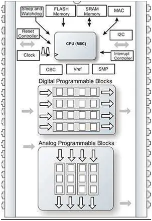
The Analog CPU unit serves as the core component of a microcontroller, responsible for executing program instructions and overseeing the operation of other blocks. The Frequency Generator produces the signals essential for the CPU’s operation, encompassing a range of frequencies utilized by programmable blocks. These signals may derive from either internal or external reference oscillators. The Reset Controller initiates microcontroller start-up procedures and restores the microcontroller to a regular state in the event of irregular occurrences.
The Watchdog Timer identifies software dead-loops, while the Sleep Timer can periodically awaken the microcontroller from power-saving modes or function as a regular timer. Analog Programmable Blocks configure analog components such as AD and DA converters, filters, DTMF receivers, as well as programmable, instrumental, inverting, non-inverting, and operational amplifiers.
Input-Output pins facilitate communication between the CPU unit, digital programmable blocks, and the external world. Digital Programmable Blocks configure digital components selected by user operations during interrupts. The I2C controller enables the hardware implementation of I2C communication. The Voltage Reference is crucial for the operation of analog components within the analog programmable blocks.
The MAC unit performs hardware-signed multiplication of 8-bit numbers. SMP, a system integral to a voltage regulator, allows, for instance, the provision of power to a PSoC microcontroller from a single 1.5V battery.
4.2.5 PSoC SUBSYSTEMS:
The following is a high level view of the hardware subsystems of a PSoC.
The Core
The PSoC® 1 core comprises:
– The M8C MCU
– Flash memory
– SRAM
– Sleep and watchdog timers
– Multiple clock sources, including a PLL.
PSoC 1 devices can feature up to two multiply–accumulate modules (MACs), offering rapid 8-bit multiplication or swift 8-bit multiplication with a 32-bit accumulation. They can also incorporate up to two decimators suitable for digital signal processing applications. Additionally, these devices support I2C functionality, allowing the implementation of either I2C slave or master, and they come equipped with a full-speed USB interface.
4.3. PIC18F452 (MICROCONTROLLER)
Originally, the acronym PIC stood for “Peripheral Interface Controller.” PICs have gained popularity among both industrial developers and hobbyists due to their affordability, widespread availability, large user community, extensive repository of application notes, accessibility of low-cost or free development tools, and the ability for serial programming and re-programming with flash memory capability. The PIC Processor features a Harvard architecture, wherein instruction memory and data memory are distinct entities.
A PIC’s instruction set varies, ranging from approximately 35 instructions for low-end PICs to over 80 instructions for high-end PICs. This set encompasses operations on registers directly, involving the accumulator and a literal constant or the accumulator and a register. It also includes instructions for conditional execution, program branching, and bit setting and testing, which can be performed on any numbered register. However, bi-operand arithmetic operations always involve the accumulator, and the result is written back to either the accumulator or the other operand register. Loading a constant requires first loading it into the accumulator (W) before transferring it to another register.
In the older cores, all register movements needed to pass through W, but this changed in the “high-end” cores. PIC cores incorporate skip instructions for conditional execution and branching, specifically ‘skip if bit set’ and ‘skip if bit not set.’ Since cores before PIC18 had only unconditional branch instructions, conditional jumps were implemented by a conditional skip with the opposite condition, followed by an unconditional branch. Skips are also useful for the conditional execution of any immediate single following instruction.
PICs feature a two-stage pipeline that runs simultaneously to enhance speed. The instruction fetch stage retrieves the next instruction machine code from program memory, while the execution stage performs the operations dictated by the machine code.
4.3.1 PERIPHERAL FEATURES
The peripheral features of the PIC18F452 microcontroller include:
– High current sink/source of 25 mA/25 mA.
– Three external interrupt pins.
– Timer0 module: 8-bit/16-bit timer/counter with an 8-bit programmable prescaler.
– Timer1 module: 16-bit timer/counter.
– Timer2 module: 8-bit timer/counter with an 8-bit period register (serving as the time-base for PWM).
– Timer3 module: 16-bit timer/counter.
– Option for a secondary oscillator clock, applicable to Timer1/Timer3.
– Addressable USART module supporting RS-485 and RS-232.
– Two Capture/Compare/PWM (CCP) modules with configurable CCP pins for:
– Capture input: capturing in 16-bit with a maximum resolution of 6.25 ns (TCY/16).
– Compare in 16-bit with a maximum resolution of 100 ns (TCY).
– PWM output: PWM resolution ranges from 1 to 10 bits, with a maximum 10-bit resolution at 39 kHz.
– Master Synchronous Serial Port (MSSP) module supporting two modes of operation:
– 3-wire SPI™ (compatible with all 4 SPI modes).
– I2C™ Master and Slave modes.
4.3.2 ANALOG FEATURES
• 10-bit Analog-to-Digital Converter module (A/D) with compatibility features such as:
– Rapid sampling rate
– Conversion capability during SLEEP mode
– Linearity within ≤ 1 Least Significant Bit (LSb)
• Programmable Low Voltage Detection (PLVD) functionality:
– Accommodates interrupts on Low Voltage Detection
• Programmable Brown-out Reset (BOR) feature
4.3.3. SPECIAL MICROCONTROLLER FEATURES
• Enhanced FLASH program memory with a typical erase/write cycle of 100,000 cycles
• Data EEPROM memory featuring a remarkable erase/write cycle endurance of 1,000,000 cycles
• FLASH/Data EEPROM Retention exceeding 40 years
• Capable of self-reprogramming under software control
• Incorporates Power-on Reset (POR), Power-up Timer (PWRT), and Oscillator Start-up Timer (OST)
• Equipped with a Watchdog Timer (WDT) having its own On-Chip RC Oscillator for reliable operation
• Programmable code protection enhances security
• Features a power-saving SLEEP mode
• Offers selectable oscillator options, including:
– 4X Phase Lock Loop (of the primary oscillator)
– Secondary Oscillator (32 kHz) clock input
• Facilitates Single-supply 5V In-Circuit Serial Programming™ (ICSP™) via two pins
• Allows for In-Circuit Debug (ICD) via two pins
4.3.4. CMOS TECHNOLOGY
• Utilizes low-power, high-speed FLASH/EEPROM technology
• Designed with a fully static configuration
• Operates across a broad voltage range (2.0V to 5.5V)
• Suitable for industrial and extended temperature conditions
• Demonstrates low power consumption:
– Typical consumption of < 1.6 mA at 5V, 4 MHz
– Typical consumption of 25 μA at 3V, 32 kHz
– Typical standby current of < 0.2 μA
– Typical consumption of < 2 mA at 7V, 5 MHz
• Exhibits flexibility and adaptability
• Applicable across a wide range of uses
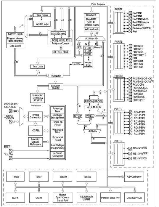
4.3.5. BLOCK DIAGRAM OF PIC 18F452
4.3.6. PIC18F452 HIGH END CORE DEVICES
Microchip introduced the PIC18 architecture in 2000, and unlike the 17 series, it has gained immense popularity with a wide range of device variants currently in production. In a departure from earlier devices, which were predominantly programmed in assembly language, the prevalent development language for the PIC18 series has shifted to C.
The PIC18 series inherits most features and instructions from the 17 series while incorporating several significant enhancements. These include a much deeper call stack capable of reaching 31 levels, allowing read and write access to the call stack. Additional features encompass conditional branch instructions, an indexed addressing mode, an extension of FSR registers to 12 bits, enabling linear addressing across the entire data address space, and the introduction of another FSR register, bringing the total to three. The auto increment/decrement feature saw improvements, with the removal of control bits and the addition of four new indirect registers per FSR. Depending on the accessed indirect file register, post-decrement, post-increment, or pre-increment of FSR is possible, or the effective address can be formed by adding W to FSR.
In more advanced PIC18 devices, an “extended mode” further optimizes addressing for compiled code, introducing a new offset addressing mode. Some addresses, previously relative to the access bank, are now interpreted relative to the FSR2 register. Several new instructions have been added, particularly for manipulating the FSR registers. These changes were aimed at enhancing the efficiency of a data stack implementation. Utilizing FSR2 as either the stack or frame pointer in Microchip’s MPLAB C18 C compiler facilitates easy indexing of stack items, enabling more efficient reentrant code.
The PIC18 series represents a shift toward C as the predominant development language, bringing forth enhancements to the call stack, addressing modes, and FSR registers, ultimately providing a dynamic and efficient series of microcontrollers.
|
Part Number |
Program
memory (16 bit words) |
RAM bytes |
Total Pins |
I/O pins |
40-pin DIP |
44-pin PLCC |
44-pin TQFP |
28-pin DIP |
28-pin SOIC |
| PIC 18F452 |
16384 |
1536 |
40/44 |
33 |
2.058”
*0.600” |
0.690*
0.690 |
0.472*
0.472 |
||
| PIC
18F442 |
8192 |
768 |
40/44 |
33 |
2.058”
*0.600” |
0.690”*
0.690” |
0.472”*
0.472” |
||
| PIC 18F252 |
16384 |
1536 |
28 |
22 |
1.345”*
0.300” |
0.704*
0.407 |
|||
| PIC
18F242 |
8192 |
768 |
28 |
22 |
1.345”*
0.300” |
0.704”*
0.407” |
Table no 4.3.2: Alternative family member parts
4.3.7 CHARACTERISTICS
• Robust Design: The I/O pins of this microcontroller are capable of driving loads up to 25 mA as outputs and are safeguarded against static electricity damage when used as inputs.
• Error Handling: For robust error recovery, the PIC18F452 incorporates a built-in watchdog timer, brown-out reset circuitry, and low-voltage detect circuitry, offering alternative methods for detecting malfunctions and addressing them.
• Low-Power Operation Support: Renowned for its power efficiency, the PIC18F452 microcontroller enhances battery life by seamlessly alternating between low-power sleep mode and normal operation intervals. The watchdog timer facilitates the creation of a low duty cycle, resulting in low average power dissipation.
• I/O Expansion Capabilities: The microcontroller’s built-in serial peripheral interface allows the utilization of standard 16-pin shift-register components to add a flexible number of I/O pins. Additionally, the integrated I2C interface supports the incorporation of specialty peripheral components.
• Mathematical Support: Microchip provides comprehensive support for the PIC18F452 microcontroller, offering various multiplication and division subroutines tailored for multiple-byte fixed-point numbers and floating-point numbers.
• Ordering Support: Digi-Key Corporation and Newark Electronics offer convenient online and telephone purchasing options for PIC18FXXX.
• Free Software Tools: Microchip promotes user engagement by providing free access to its MPLAB® Integrated Development Package application notes, available on their website.
• Development Tool Versatility: The PIC18F452 microcontroller’s flash program memory supports a standard emulator with trace information capture capability. Furthermore, it accommodates a low-cost in-circuit debugger and a cost-free QwikBug monitor program.
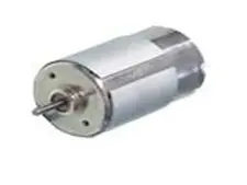
4.4 DC MOTOR
A DC motor is an electric motor powered by direct current (DC) electricity. Historically, DC motors were employed to drive machinery, often obviating the need for local steam engines or internal combustion engines. These motors could function directly from rechargeable batteries, thus serving as the driving force for the earliest electric vehicles. Presently, DC motors continue to find applications ranging from small-scale toys and disk drives to larger sizes operating in steel rolling mills and paper machines. In contemporary settings, DC motors are typically operated alongside power electronic devices.
Similar to all electric motors and generators, torque is generated in a brushed DC motor through the Lorentz force principle. According to this principle, any current-carrying conductor placed in an external magnetic field experiences a torque or force, known as Lorentz force. Brushed DC motors offer advantages such as low initial cost, high reliability, and straightforward control of motor speed. However, they come with disadvantages, including high maintenance requirements and a relatively short lifespan under intense usage. Maintenance involves regular replacement of brushes and springs that carry the electric current, as well as cleaning or replacing the commutator.
4.4.1. SERIES CONNECTION
A DC motor of the series type connects both the armature and field windings in series with a common DC power source. This motor exhibits poor speed regulation, as its speed tends to vary inversely with the load. Despite this limitation, a series DC motor boasts high starting torque, making it suitable for initiating high-inertia loads like trains, elevators, or hoists. When the series motor operates with no mechanical load, the current is low, resulting in a weak magnetic field from the field winding. Consequently, the armature must rotate at a faster rate to generate adequate counter-electromotive force (EMF) and balance the supply voltage.
In some motor types, there may be a risk of exceeding a safe and sustainable speed, leading to a condition known as runaway. This phenomenon is particularly relevant in applications like dragline excavators, where the speed/torque characteristic determines the tool’s movement speed under varying loads.
Series motors, also known as “universal motors,” can operate on alternating current (AC). Since the armature voltage and field direction reverse simultaneously, torque continues in the same direction. Universal motors, not tied to the line frequency, can achieve speeds higher than synchronous speeds, making them lighter than induction motors with similar mechanical output ratings. This characteristic is especially advantageous for hand-held power tools. Although commercial power frequency universal motors are typically small, larger versions were employed in the past. These larger universal motors were supplied by specialized low-frequency traction power networks to address commutation challenges under heavy and fluctuating loads.
4.4.2. SHUNT CONNECTION
In a shunt DC motor, the armature and field windings are connected in parallel, or shunt, utilizing a shared DC power source. This motor design exhibits effective speed regulation, maintaining a consistent speed despite load fluctuations. However, it does not possess the same high starting torque capabilities as a series DC motor. Shunt DC motors find common application in industrial settings, especially in adjustable scenarios like machine tools, winding/unwinding machines, and tensioners.
4.4.3. COMPOUND CONNECTION
A compound DC motor combines the armature and field windings in both shunt and series configurations, exhibiting characteristics of both types. This motor is employed in applications requiring both high starting torque and effective speed regulation. There are two possible connections for this motor: cumulative and differential. Cumulative compound motors connect the series field to support the shunt field, resulting in higher starting torque at the expense of speed regulation.
This motor is utilized when a balance between high starting torque and good speed regulation is essential. The two available arrangements, cumulative or differential, offer distinct characteristics. Cumulative compound motors augment the shunt field with the series field, providing elevated starting torque but compromising speed regulation. In contrast, differential compound DC motors offer superior speed regulation and are commonly operated at a constant speed.
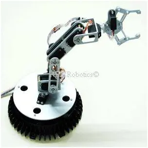
4.5. ROBOTIC ARM
4.5.1 Description
A robotic arm, typically programmable, serves as a robotic manipulator with functionalities akin to a human arm. Joint rotation is facilitated by servo motors, and the arm possesses a comparable number of degrees of freedom as a human arm. While humans instinctively perform actions like picking up objects without consciously considering the steps involved, a robot or robotic arm requires explicit instructions. To manipulate or pick up an item, the robotic arm needs a set sequence of actions, including moving the arm, rotating the “wrist,” and opening or closing the “hand” or “fingers.” Therefore, each joint of the robotic arm can be controlled through a computer interface.
4.5.2 Overview
• Number of Degrees of Freedom: 4
• Payload Capacity (Fully Extended): 150 grams
• Maximum Reach (Fully Extended): 35 centimeters
• Rated Speed (Adjustable): 0-0.3 meters per second
• Joint Speed (Adjustable): 0-60 revolutions per minute (rpm)
• Hardware Interface: USB
• Control Software: Computer Interface (Graphical User Interface – GUI)
• Shoulder Base Spin: 180 degrees
• Shoulder Pitch: 180 degrees
• Elbow Pitch: 180 degrees
• Wrist Pitch: 180 degrees
• Gripper Opening (Maximum): 8 centimeters
4.5.3 Sailent features / innovations
1. The arm is powered by a single ATmega 16 microcontroller, efficiently controlling all five servos.
2. With a grabbing range extending approximately 50cm in a hemisphere, the arm is sturdily constructed using a 2.5mm aluminum sheet.
3. The arm boasts user-friendliness through our developed computer interface, making it accessible even for individuals with minimal experience.
4. It has the capacity to lift objects weighing up to 200 grams.
5. The base rotation is achieved without the need for gears or ball bearings, utilizing low-torque servo motors and three castor wheels for the overall rotation.
6. The graphical user interface is crafted using functions, departing from the previously employed Matlab approach.
7. The design of the robotic arm gripper is intentionally kept simple, implementing a gripping mechanism without gears, using only one servo motor.
What are Servo Motors?
A servo denotes a feedback control system employed to rectify the performance of a system. Servo or RC (Radio Control) Servo Motors are DC motors integrated with a servo mechanism to achieve accurate control over angular position. Typically, RC servo motors exhibit a rotational range limited to 90° to 180°. It’s important to note that servos do not undergo continuous rotation; instead, their movement is confined within specific fixed angles.
Where are Servos used?
Servo motors are employed for precise positioning and find applications in various devices such as robotic arms, legs, sensor scanners, and RC toys like helicopters, airplanes, and cars. The wiring and plugs of servo motors typically consist of three wires. Two of these wires are designated for providing ground and positive supply to the servo DC motor, while the third wire is dedicated to the control signal. The color-coding of these wires may vary among manufacturers.
Specifically, the red wire serves as the DC supply lead, requiring connection to a DC voltage supply within the range of 4.8V to 6V. The black wire is utilized for grounding purposes. The color of the third wire, which delivers the control signal, varies; it could be yellow (for Hitec), white (for Futaba), brown, etc. Futaba servos typically come with a J-type plug featuring an extra flange for secure connection, while Hitec utilizes an S-type connector. Compatibility between Futaba and Hitec connectors can be achieved by modifying the connectors accordingly.
It’s crucial to note that Hitec splines consist of 24 teeth, whereas Futaba splines have 25 teeth. Consequently, splines designed for one servo type cannot be interchanged with another. The spline is where a servo arm is attached, analogous to the shaft of a conventional DC motor. Unlike DC motors, swapping the ground and positive supply connections does not alter the rotation direction of a servo; in fact, it may damage the servo motor. Thus, proper consideration of the wire order in a servo motor is essential.
Servo Control
A servo motor is primarily composed of a DC motor, a gear system, a position sensor (usually a potentiometer), and control electronics. The DC motor is linked to a gear mechanism that provides feedback to a position sensor, typically a potentiometer. The motor’s output from the gearbox is transmitted via a servo spline to the servo arm. The potentiometer adjusts its position in tandem with the motor’s current position, causing a change in resistance that corresponds to a voltage shift. A pulse width-modulated (PWM) signal is transmitted through the control wire. The pulse width is converted into a voltage equivalent, compared with the signal from the potentiometer in an error amplifier.
To position the servo motor at a desired angle, PWM signals are sent on the control wire. The servo comprehends pulse position modulation, with pulses ranging from 1 millisecond to 2 milliseconds repeated about 50 times per second. The pulse width dictates the angular position, where, for instance, a 1-millisecond pulse moves the servo towards 0°, and a 2-millisecond pulse shifts it to 180°. Pulse widths between these values can be interpolated, such that a 1.5-millisecond pulse positions the servo at 90°. It’s important to note that these values are approximations, and actual servo behavior may vary based on the manufacturer.
To maintain a specific angular position, a sequence of such pulses (50 per second) must be sent to the servo. Upon receiving a pulse, the servo retains the corresponding angular position for the next 20 milliseconds. Therefore, a pulse must be fed to the servo every 20 milliseconds. Generating the required pulse train for servo motor control can be achieved using a timer IC like 555 or by programming a microcontroller to produce the necessary waveform. For additional information, refer to Servo Motor interfacing with 8051 microcontroller and Servo control using AVR ATmega16.
The Dexter ER1 Robotic Arm is a sophisticated 5-axis robotic arm equipped with a servo gripper. It is powered by four robust metal gear servo motors boasting 15Kg/cm torque and two additional servo motors with 7Kg/cm torque. The arm provides 5 degrees of freedom, encompassing base rotation, shoulder rotation, elbow rotation, wrist pitch, and roll. The arm is delivered fully assembled and includes a versatile servo motor controller capable of concurrently managing 32 servo motors with velocity trajectory profiles. The package is complemented by an advanced graphical user interface (GUI) for robotic arm motion profiling and a 5V-25A, 12V-5A Switched-Mode Power Supply (SMPS).
Crafted from high-grade machined and injection-molded aluminum alloy, the robotic arm incorporates four NRS-995 17Kg/cm dual-bearing metal gear servo motors and two lightweight micro servo motors.
The included 32-channel universal servo motor controller board and GUI offer comprehensive control over all aspects of the arm. The GUI allows for real-time control of each axis and facilitates the teaching of motion sequences using a mouse. The robotic arm interfaces seamlessly with a PC through a USB port, enabling programming for diverse motion profiles across all five servo channels simultaneously.
- How does the glove detect hand movements?
Flex sensors change resistance when bent; this resistance is converted to a voltage using a voltage divider and measured by ADCs. - Can the PSoC measure the flex sensor outputs directly?
Yes, PSoC analog programmable blocks and the Delta Sigma ADC digitize the analog flex sensor voltages for processing. - What microcontrollers are used to control the robot arm?
The project uses PSoC family MCUs (M8C core) for sensor ADC and UART tasks and PIC microcontrollers (PIC16F877A, PIC18F452, PIC16F628A referenced) to drive motors and coordinate the arm. - Does the project use a motor driver IC for stepper control?
Yes, the PIC16F877A coordinates with the L293D IC to control the stepper motor drive. - What determines the robot arm motion corresponding to glove input?
The sequence and frequency of input pulses determine rotation direction, length, and speed; flex sensor-derived signals are digitized and translated into control pulses for motors. - How many degrees of freedom does the robotic arm have?
The described robotic arm provides five axes of movement and in one overview lists 4 degrees of freedom for a variant; five-axis capability is emphasized for pick-and-place tasks. - Can the robot be controlled remotely from a PC?
Yes, the system supports PC commands via USB and UART interfaces and includes a GUI for remote control and motion profiling. - What advantages does PSoC offer in this system?
PSoC provides configurable analog and digital blocks, ADCs, UARTs, programmable amplifiers, and flexible I/O allowing integration of sensor conditioning and communication on-chip. - How are servo positions commanded?
Servos receive PWM pulses (approximately 1–2 ms width at ~50 Hz); pulse width maps to angular position (e.g., 1 ms ~0°, 1.5 ms ~90°, 2 ms ~180°). - What sensors are proposed for autonomous navigation and object detection?
The project proposes integrating ultrasonic range finders and color/object detection sensors to enable obstacle avoidance and object identification.