Summary of Stepper Motor Control using 8051 Microcontroller
Summary: The project demonstrates interfacing an 8051 (AT89C51) microcontroller with a bipolar or unipolar stepper motor using L293D and ULN2003 drivers. It explains stepper motor types, half-stepping control, circuit design steps, and component connections for LCD, crystal, reset, push buttons, and motor drivers to safely supply current and achieve precise incremental rotation.
Parts used in the Stepper Motor Control using 8051 Microcontroller:
- AT89C51 (8051 Microcontroller)
- L293D Motor Driver
- ULN2003A
- 5V Bipolar Stepper Motor
- Stepper Motor (6-pin) for ULN2003A circuit
- 16x2 LCD Display
- 11.0592 MHz Quartz Crystal
- 33pF Ceramic Capacitors (x2)
- 10KΩ Resistors (x2)
- 10KΩ Potentiometer
- 8x 1KΩ Resistor Pack
- 10μF/16V Capacitor
- Push Buttons (x4)
- 330Ω Resistor
- Resistor (unspecified) for ULN2003A circuit
- 5V Power Supply
I. Summary
The core concept behind the project and its circuitry involves incrementally rotating a stepper motor by a specific step angle. To accomplish this, the project will employ an ULN2003 IC in conjunction with the L293D Motor Driver. This combination is necessary because the controller lacks the capacity to supply the current demanded by the motor.
II. Objectives
We’ll explore the process of interfacing a stepper motor with an 8051 Microcontroller, delving into the fundamentals of stepper motors and their operational principles.
III. Industry-Based Applications
Stepper motors find versatile applications across a broad spectrum of projects. These motors play essential roles in various industries, such as automotive, where they are utilized in vehicle gauges and automated production equipment for machine tooling. Stepper motors are integral components in the medical field, powering devices like scanners, samplers, digital dental photography equipment, fluid pumps, respirators, and blood analysis machinery. They are also prevalent in technology, featuring in disk drives, matrix printers, and more. Beyond this, stepper motor circuits can be harnessed for a range of applications, from robotics to mechatronics, expanding their utility across diverse domains.
Project Methodology
A stepper motor is a type of brushless DC motor capable of rotating in small, discrete angles, referred to as “steps.” Typically, these motors are configured to take 200 steps to complete a full 360-degree rotation, equating to 1.8 degrees per step. Stepper motors find applications in various devices requiring precise rotational control, such as robots, antennas, hard drives, and more. By providing specific instructions, we can accurately position the stepper motor at any desired angle.
Stepper motors are classified into two main categories: Unipolar and Bipolar. In the case of a Unipolar stepper motor, it typically consists of either five or six wires. Four of these wires are connected to one end of the four stator coils, while the other ends of these four coils are joined together to create the fifth wire, known as the common wire.
On the other hand, Bipolar stepper motors have a simpler configuration with just four wires emerging from two separate sets of coils. This means there are no common wires in a Bipolar stepper motor.
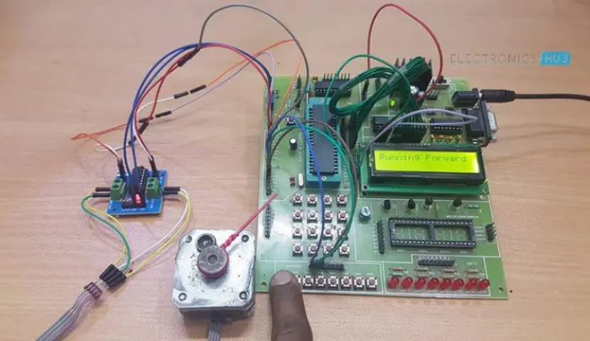
The operation of this circuit is quite straightforward. It utilizes a technique known as “Half-Stepping” within the program to control the rotation of the Stepper Motor. Pressing the forward button causes the stepper motor to rotate in a clockwise direction.
Project Outline:
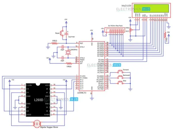
Schematic 1: Integration of an 8051 Microcontroller and L293D for Bipolar Stepper Motor Control
Components Used:
– AT89C51 (8051 Microcontroller)
– L293D Motor Driver
– 5V Bipolar Stepper Motor
– 16X2 LCD Display
– 11.0592 MHz Quartz Crystal
– 10KΩ Resistors (x2)
– 10KΩ POT (Potentiometer)
– 8x 1KΩ Resistor Pack
– 33pF Ceramic Capacitors (x2)
– 10μF/16V Capacitor
– Push Buttons (x4)
– 330Ω Resistor
– 5V Power Supply
Circuit Design:
To construct the circuit, we follow these steps:
1. Connect the data pins of the LCD to the PORT0 Pins of the AT89C51 (8051 Microcontroller). Since PORT0 doesn’t have internal pull-ups, a resistor pack is employed to provide pull-up resistors for PORT0. The RS and E pins of the LCD are linked to P2.0 and P2.1 of the 8051.
2. The RST (Reset) Pin is pulled down using a 10KΩ resistor. To reset the microcontroller, a combination of a Push Button and a 10μF Capacitor is utilized. Additionally, the EA (External Access) Pin is pulled up using a 10KΩ resistor.
3. The oscillator setup involves the use of two 33pF Capacitors and an 11.0592 MHz Crystal connected between the XTAL1 and XTAL2 Pins of the 8051 microcontroller.
4. Moving on to the Motor Driver, both enable pins and supply pins are connected to a +5V power supply. The four inputs are linked to PORT1 pins of the 8051, specifically P1.0, P1.1, P1.2, and P1.3. The four pins of the Bipolar Stepper Motor are connected to the four output pins of the L293D Motor Driver.
5. Three push buttons are connected to PORT3 pins, namely P3.0, P3.1, and P3.2, to control the direction of the Stepper Motor.
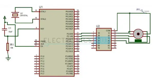
Circuit 2: Stepper Motor Control using 8051 Microcontroller & ULN2003
Circuit Components
– AT89C51 Microcontroller
– ULN2003A
– Stepper Motor
– Crystal
– Resistor
– Capacitor
Circuit Design
The circuit is composed of an AT89C51 microcontroller, ULN2003A, and a stepper motor. The AT89C51 is an energy-efficient, high-performance CMOS 8-bit microcontroller belonging to the 8051 family, featuring 32 programmable I/O lines. It is equipped with 4K bytes of flash memory that can be both programmed and erased. An external crystal oscillator is linked to pins 18 and 19 of the microcontroller. The motor is connected to Port 2 of the microcontroller through a driver IC.
The ULN2003A serves as a current driver integrated circuit, primarily employed to regulate the current supplied to a stepper motor, as these motors demand more than 60mA of current. It functions as an array of Darlington pairs, featuring a total of seven Darlington pairs with a common emitter.
This IC comprises 16 pins, with 7 dedicated to input, 7 to output, and the remainder serving as VCC and Ground connections. The first four input pins establish a connection with the microcontroller, while the four output pins are linked to the stepper motor.
A typical stepper motor possesses six pins, with two connected to a 12V power source, and the remaining pins linked to the output of the stepper motor. The stepper motor rotates in discrete steps, with each step representing a fraction of a complete rotation cycle. This step size is contingent on the mechanical components and the driving technique employed.
As with all motors, stepper motors are composed of a stator and rotor. The rotor features a permanent magnet, while the stator contains a coil. A fundamental stepper motor design includes four coils, each with a 90-degree rotation step. These four coils are activated in a cyclic sequence, determining the direction of the shaft’s rotation. There are various methods to drive a stepper motor, and some of these are elaborated below:
1. Full Step Drive: In this method, two coils are energized simultaneously.
2. Half Step Drive: This approach involves alternating energization of the coils, resulting in a half-step angle rotation. This can be achieved by energizing two coils at once or a single coil individually, thereby increasing the number of rotations per cycle.
Source: Stepper Motor Control using 8051 Microcontroller
- How does the project rotate the stepper motor by specific step angles?
The controller uses half-stepping in the program to energize coils in sequence, producing discrete step angles for precise rotation. - Can the 8051 supply current directly to the motor?
No. The controller cannot supply the required motor current, so driver ICs (L293D or ULN2003A) are used. - What motor driver is used for a bipolar stepper motor in this project?
The L293D motor driver is used for bipolar stepper motor control in Schematic 1. - What is the role of the ULN2003A in the circuit?
The ULN2003A acts as a current driver (Darlington pair array) to regulate and supply the higher current demanded by the stepper motor. - How is the LCD connected to the AT89C51?
LCD data pins connect to PORT0 with a resistor pack for pull-ups; RS and E pins connect to P2.0 and P2.1 respectively. - Which pins of the 8051 connect to the L293D inputs?
The L293D inputs are connected to PORT1 pins P1.0, P1.1, P1.2, and P1.3 of the 8051. - How are push buttons used to control motor direction?
Three push buttons are connected to PORT3 pins P3.0, P3.1, and P3.2 to control the stepper motor direction. - What oscillator components are required for the AT89C51?
An 11.0592 MHz crystal with two 33pF capacitors is connected between XTAL1 and XTAL2. - What drive methods for stepper motors are described?
The article describes full step drive, where two coils are energized, and half step drive, which alternates single and dual coil energization for half-step rotation.