Summary of Pico Timer Project using Pico with Proteus Simulation
This project shows how to use the Raspberry Pi Pico RP2040 Timer in MicroPython within a Proteus VSM simulation to blink the onboard LED at 1 Hz using a periodic timer callback, demonstrating non-blocking, interrupt-style embedded firmware suitable for beginners.
Parts used in the Pico Timer Project using Pico with Proteus Simulation:
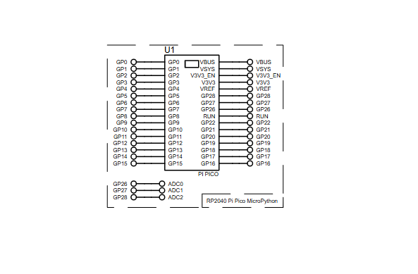
- Raspberry Pi Pico (RP2040)
- Onboard LED (built into the Pico)
- Timer module (software/hardware Timer on RP2040)
- Proteus VSM MicroPython simulation environment
- MicroPython runtime
- How does the project blink the LED?
The Timer is configured in periodic mode at 1 Hz and its callback function blink() toggles the onboard LED each second. - Can this be simulated without physical hardware?
Yes, the project runs in Proteus VSM for MicroPython and simulates the Pico executing the firmware. - What frequency is the timer set to?
The timer is set to 1 Hz, triggering once every second. - Does the main program use delay loops?
No, the main loop remains essentially empty because the timer callback handles blinking without blocking delays. - What MicroPython modules are used in the code?
The code imports Pin and Timer from the machine module. - What hardware components are required externally?
No external components are required since the Pico’s built-in onboard LED is used for visualization. - What is the purpose of the blink() function?
blink() is the timer callback that checks and toggles the LED state each time the timer fires. - Is this project suitable for beginners?
Yes, the project is described as beginner-friendly and useful for learning MicroPython, Proteus simulation, and basic firmware design.