Summary of Efficient Multichannel Data Acquisition with USB Connectivity using PIC Microcontroller
This article describes a USB-based multichannel data acquisition system (DAS) using the PIC18LF4553 microcontroller, a 12-bit 13-channel ADC, and FT232R USB-UART interface to stream accelerometer data to a MATLAB PC application for real-time plotting and storage. The system samples at 21 Hz, achieves 1.22 mV resolution with a 5 V reference, and uses UART at 460800 baud with a simple Start...end 28-character data string protocol. The design is low-cost, compact, and adaptable for monitoring and control applications.
Parts used in the USB-based multichannel DAS:
- PIC18LF4553 microcontroller (40-pin, 12-bit ADC)
- FT232R USB to serial UART interfacing IC
- LIS3L02AS4 tri-axis accelerometer sensor
- Potentiometer (POT meter)
- USB cable (power and data)
- Programmer supporting ICSP for PIC (In-Circuit Serial Programming)
- PC or laptop running MATLAB application
- Miscellaneous circuit components (PCB, connectors, wiring)
1. INTRODUCTION
With the rapid advancements in embedded technology, there is a growing demand for a data acquisition system that combines fast processing speed, compact size, low cost, and real-time data monitoring capabilities. The utilization of a microcontroller as a processor has gained popularity due to its speed, energy efficiency, affordability, and lightweight nature [1-2]. This popularity has led to its widespread use in Data Acquisition Systems (DAS).
A Data Acquisition System is employed to continuously acquire signals from physical parameters over a specific period, recording these values for future reference. Typically, a DAS consists of a primary control and data processor, memory, and a clock/calendar module for time-stamping the acquired data. Various sensor attachments are necessary depending on the application. Since internal processors are primarily digital, analog signals are often converted to digital format before processing [1]. For analysis, display, and recording, the processor is connected to a computer or laptop. The complexity of a DAS system increases with the number of physical properties to be measured, the resolution of the Analog-to-Digital Converter (ADC), and the required accuracy and speed of measurement.
This work presents the design and development of a USB-based DAS system utilizing the PIC18LF4553 microcontroller. The PIC18LF4553 microcontroller is well-suited for low-power applications, featuring a 13-channel 12-bit ADC and three serial ports: USB, SPI, and an asynchronous serial port [3]. The USB interface with the computer is preferred due to its high data transmission rate and easy connectivity. Therefore, the designed USB-based multichannel DAS system offers high computational performance at an economical price [4-6].
2. HARDWARE DESIGN
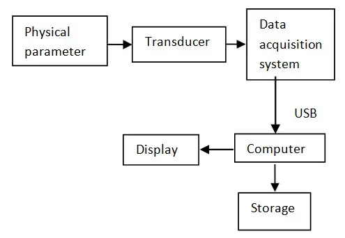
The proposed design’s block diagram is illustrated in Figure 1. To illustrate, the designed Data Acquisition System (DAS) is employed to monitor accelerometer values as a case study. The circuit diagram, including the transducer, is depicted in Figure 2. The subsequent sections provide details on the hardware, firmware, and software components for the real-time monitoring DAS.
Data Acquisition Unit
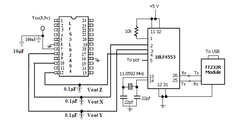
The development of the data acquisition system utilized the PIC 18LF4553, a mid-range 40-pin, high-performance microcontroller featuring enhanced flash and USB capabilities, along with a 12-bit A/D converter. The circuit is powered directly from the PC via a USB cable. With 13 ADC channels and 12-bit resolution, the PIC efficiently processes analog signals applied to its ADC inputs. The 12-bit resolution enables the system to read signals in 4096 steps, providing a high level of precision. The reference voltage applied to the ADC is 5 volts, resulting in an accuracy of 1.22mV.
Sensors
The converted data is sent to the PC through the utilization of FT232R, a USB to serial UART interfacing IC. The LIS3L02AS4 sensor is proficient in measuring tri-axis linear acceleration, incorporating a sensing element and an IC interface that delivers an analog signal representing the measured acceleration value to external devices. It can measure accelerations across a maximum bandwidth of 4.0 KHz for the X and Y axes and 2.5 KHz for the Z axis. The IC interface comes factory calibrated, ensuring that the end user receives a pre-configured device ready for operation.
Firmware
Data transfer to the PC occurs through a USB to serial UART interfacing IC, with the USB serving as the interface on the PC side. The IC, FT232R, emulates a virtual serial port on the PC, while on the Data Acquisition System (DAS) side, data is transmitted to the UART of FT232R. Consequently, communication on the DAS side relies on the microcontroller’s UART. Utilizing FT232R offers the advantage of USB portability, simplifying the communication code to only UART, avoiding the need for complex USB code. The PIC program, coded in C language, is compiled in mikroC to produce a Hex file. This Hex file is then transferred to the PIC 18LF4553 microcontroller using In-Circuit Serial Programming (ICSP).
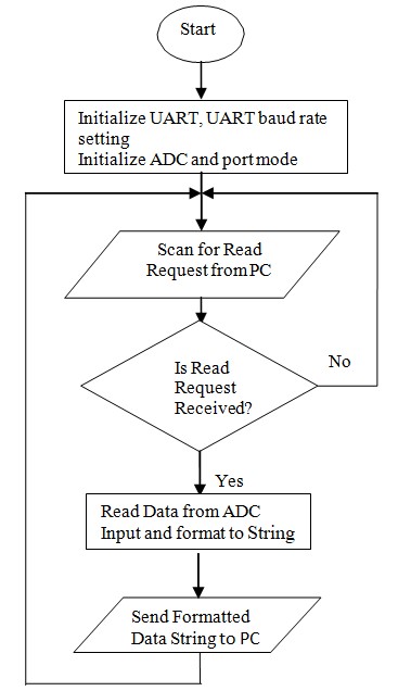
The UART baud rate is set at 460800 to optimize data transfer speed, and communication through UART is asynchronous. The PC application initiates the data acquisition system, requesting data from the DAS by sending the character ‘r’ through UART. Upon receiving ‘r,’ the DAS reads analog input channels and formats the digitized data into a 28-character string: “Start12345123451234512345end.” The string begins with “Start,” indicating its start, followed by five characters representing the decimal value of the 12-bit ADC for channel 0. Subsequently, each set of five characters represents data for a specific channel. In this DAS system, code has been developed for four analog input channels. After the fourth channel’s data, the string concludes with the character sequence “end” denoting its end. The program’s flowchart is depicted in figure 3.
Application Program
A MATLAB-based PC application program has been created to facilitate the efficient acquisition, real-time graphical display, and storage of acquired data into a file. The application program interacts with the USB device, treating it as a standard COM port device of the PC [8]. This program is designed to capture data for a user-defined time duration.
Upon initiation, the program transmits the ‘r’ character to the Data Acquisition System (DAS). Subsequently, the DAS sends the data string to the PC. The application program performs error checking on the received data string, employing a straightforward methodology. Initially, the string length is examined, requiring it to be 28 characters. If the length is correct, the program checks for the presence of the character sequence “Start” at the beginning and “end” at the end of the string. If no errors are detected, the data string is deemed valid and processed to extract analog voltages from all channels.
The analog voltages are presented in real-time through plotting and are concurrently stored in the MATLAB workspace. The application program then prompts the DAS for another data string, and this process repeats for the specified user-defined time duration. After completing the acquisition period, the application program saves the accumulated data in the workspace to a file within the PC environment for future reference.
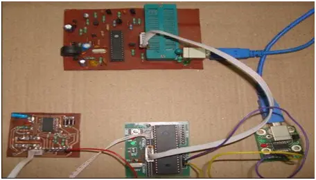
In this specific setup, the output of an accelerometer module is linked to three channels of the Analog-to-Digital Converter (ADC). The accelerometer undergoes displacement along all axes. The fourth channel of the ADC is connected to a potentiometer (POT meter) with a constant applied voltage. Figure 4 provides a visual representation of the developed Data Acquisition System (DAS) alongside the sensor and programmer. Additionally, Figure 5 displays a snapshot of the real-time plot during the data acquisition process.
3. RESULT AND DISCUSSION
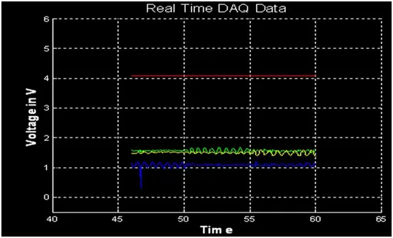
Data was gathered over a 60-second interval and is presently being displayed in real-time on the MATLAB figure window. Simultaneously, the collected values are being saved in a text file. Throughout the assigned 60-second acquisition period, the Data Acquisition System (DAS) has recorded approximately 1282 samples. The sample rate for this developed DAS system has been determined to be 21 samples per second.
In Figure 5, the plotted waveform illustrates the three outputs (represented by the blue line, yellow line, and green line in the figure window) corresponding to the accelerometer’s X-axis, Y-axis, and Z-axis, along with the constant voltage value across the POT meter (depicted by the red line). Variations in acceleration along each axis are clearly observable in the acquired data displayed in the plotted figure. The consistent red line signifies the unchanging voltage level across the POT meter.
4. CONCLUSION
This system finds applicability in various domains such as inertial navigation, vibration monitoring, appliance control, and robotics, where the need for measurement, monitoring, and data storage arises. The devised system is characterized by its cost-effectiveness and compact design, featuring a 12-bit resolution with an accuracy of 1.22mV. Additionally, it seamlessly integrates with PCs and laptops, making it compatible through a standard USB port. The Analog-to-Digital Converter (ADC) includes 13 channels, enabling simultaneous data acquisition from 13 distinct signals. Through minor software adjustments, the system can also be repurposed for control applications by utilizing the available digital input and output pins.
- What microcontroller is used in the DAS?
The DAS uses the PIC18LF4553 microcontroller with a 12-bit A/D converter and USB capability. - How does the DAS connect to the PC?
The DAS connects to the PC via USB using the FT232R USB to serial UART interfacing IC which emulates a COM port. - What sensor is used for acceleration measurement?
The LIS3L02AS4 tri-axis accelerometer sensor is used to provide analog acceleration signals. - What is the ADC resolution and accuracy?
The ADC is 12-bit (4096 steps) with an accuracy of 1.22 mV using a 5 V reference. - What baud rate is used for UART communication?
The UART baud rate is set at 460800 for optimized data transfer. - How does the DAS format data sent to the PC?
Upon request, the DAS sends a 28-character string starting with Start, followed by five-character values for each channel, and ending with end. - How is the firmware programmed into the PIC?
The compiled Hex file from mikroC is transferred to the PIC18LF4553 using In-Circuit Serial Programming ICSP. - What software is used on the PC to display and store data?
A MATLAB-based application acquires, plots in real time, performs simple error checks, and saves data to a file. - What sample rate was achieved in testing?
The developed DAS recorded about 1282 samples in 60 seconds, giving a sample rate of 21 samples per second. - Can the system be repurposed for control applications?
Yes, with minor software changes the available digital I/O pins can be used for control applications.