- What you will learn
1.1. How to create a project using MPLAB.
1.2. How to link the files necessary to build a hex file.
1.3. How to simulate operation of the file.
1.4. How to emulate the microcontroller using MPLAB ICE 2000.
1.5. How to program the microcontroller using the BPMICROSYSTEMS BP-1400.
- Setting up your environment
2.1. First, it is recommended that you create an separate directory under your class account to hold the designs for the tutorial. Open a DOS window and type the following:
cd\
cd students
mkdir
cd
mkdir tutorial
cd tutorial
mkdir arm
cd arm
2.2. Copy the files robot.c and dy100tcx.asm from the directory c:\mcc\examples\robot into your directory.
copy c:progra~1\mplab\mcc\examples\arm\arm.c .
2.3. Open the arm.c file in the notepad to examine it.
This program generates a pulse for each of the three movements of the robotic arm. The robot operates on a pulse that is transmitted to each servo. The pulse can be between .5 and 2.5ms. A 1.5ms pulsewidth centers the servo. The program calls two header files. One for the 17C44 microcontroller and the the other for the delays. The define statements are constants that are inserted into the body of the code when it is compiled and do not count as memory. Any constant you want to use should be a define statement. All of the variables are defined and set to intial values to center the robotic arm. DDRC = 0x00 sets port C as an output. The output pulses will control the robotic arm. A high signal is generated and the code then goes through a delay, the length of which determines the generated pulse width. The output is then set low. This process is repeated for the other two servos in the arm. The value of the three pulses is added and then subtracted from 10 ms to generate the overall loop delay. This insures a stable pulse repetition rate.- Creating the project for control of the robotic arm
3.1. Start the MPLAB IDE (Integrated Development Environment) by double clicking on the MPLAB icon inside the Microchip MPLAB folder on the desktop.
3.2. Create a new project by selecting Project->New Project from the main window menus. Navigate to your c:\students\\tutorial\arm directory and set the file name to arm.pjt. This will bring up the Edit Project box and make the Target Filename arm.hex as shown below.
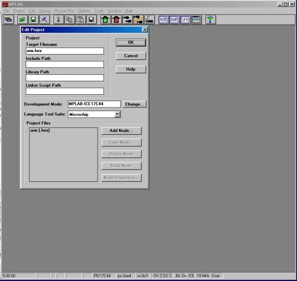
3.3. Click on arm.hex and then click on Node Properties. The Node Properties box will come up. Change the Language tool to MPLINK. Click OK.
3.4. In the Edit Project box click Add Node. Choose folder C:\Students\\tutorial\arm\ click on the arm.c file and click OK.
3.5. Click Add Node again. Choose folder C:\progra~1\mplab\mcc\lib\ and change the file types to .o object files. Add files c0s17.o, idata17.o and p17c44.o. Click OK.
3.6. Click Add Node. Choose folder C:\progra~1\mplab\mcc\lkr\ and change the file type to .lkr linker files. Add node p17c44s.lkr.
3.7. Click Add Node. Choose folder C:\progra~1\mplab\mcc\src\pmc\ and change the file type to .c, .asm source files. Add node dy100tcx.asm. Click OK The screen should look similar to the one below:
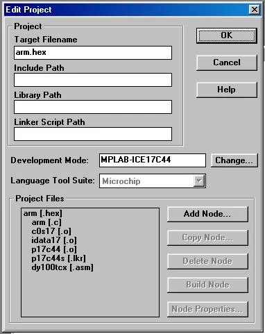
3.7. Click OK. Select Project->Make Project. The program will now link and assemble all of the necessary files. A Build Results window will come up showing the files being compiled. The last line in the Build Results window should say “Build completed successfully.”
- Simulation of the Program
The MPLAB IDE includes a simulator that allows you to simulate the program you just compiled. This allows you to verify that the program works properly. It also allows you to view the contents of memory, the stack, variables and special registers as the program is running. In addition, it allows you to setup input stimulous to test the function of your I/O routines.
4.1. Add a trace of the “yaw” variable in the program by selecting Debug->System Reset. Select Window->New Watch Window. In the window type yaw and click Add. The default value is Hex. If you want to change it click on properties and then click on decimal. Do the same with pitch and grip. Click OK.
4.2. Force values on the RD0 and RD1 inputs to the microcontroller by selecting Debug->Simulator Stimulus->Asynchronous Stimulus. The pins in the dialog box must be assigned by right clicking and selectin Assign Pin… from the pop up menu. Select RD0 and RD1 by double clicking on them. Assign RD0 a value of low by right clicking on its button. Assign the RD1 a value of high the same way. The screen should look similar to this:
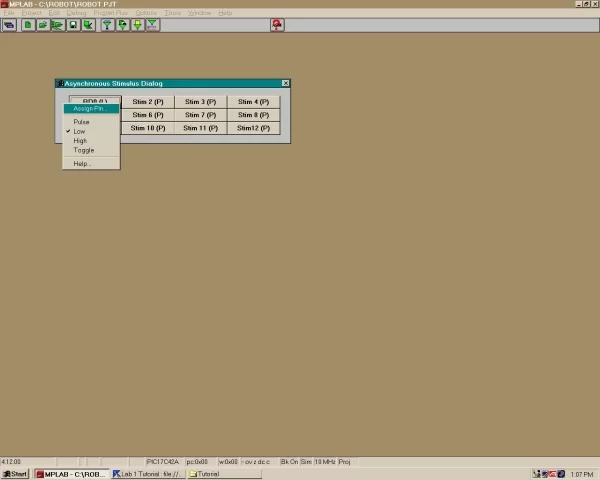
This can be done for any of the pins RD0 – RD5. This will simulate pushing a button on the test board.
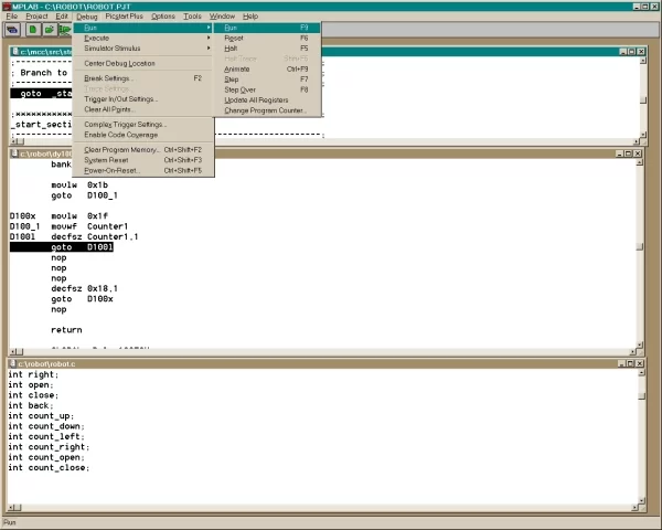
4.3. Click on Debug->Run->Stepor push the F7 key. Push the F7 key a few times and several windows will open as the program steps into other ares of the code. The screen will look like the following:
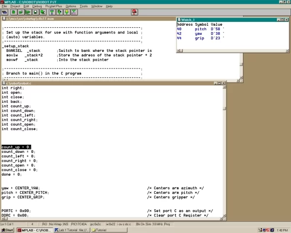
As you push F7 you should see the program stepping through the lines of the program.
4.4. Double click on the RD1(H) button. The program will pass over the if up loop. It should go down into the if down loop. As you keep pushing F7, it will start the delay loop and bring up another window dy100tcx.asm. This is the code for the delay of the pulse width to drive the robotic arm. At this point, single stepping the program is no longer useful as it would take too long to run through the entire delay. Save and exit the program.
- Emulation of the microcontroller on the robotic arm board
This will emulate the microcontroller on a test board. It allows the board to be tested verifying the functionality of the hardware and software. Adjustments to the code can be made and recompiled to insure the ultimate performance of the microcontroller. Be sure to be grounded before touching any part of the emulator as it is static sensitive. Be sure to take caution when handing the emulator as not to bend any of the pins.
5.1. Turn on the MPLAB ICE 2000. Start the MPLAB Program.
5.2. Plug emulator into test board socket carefully. Assure the power supply voltage is set at 5.0 volts and connect the leads to the control board.
5.3. Select Project->Open Project and select your robot.pjt file. Whatever windows were up when project was saved will come up when it is opened.
5.4. Setup the MPLAB system for emulation by selecting Options->Development Mode… Select MPLAB-ICE Emulator in the dialog box and click Reset. The lights on the MPLAB-ICE emulator should flash and the red H light should be eluminated. The system is now reset and ready to run. Click Debug->Run->Run or push the F9 key to start the program. The robotic arm should move the the center postion for the pitch, yaw and grip. The robotic arm should move in the direction as you push the buttons. It will stop moving in whichever direction if it reaches the limit set in the software or both buttons are pressed simutaneously.
5.5. Connect oscillioscope the signal pins of the servos (yellow wire to the servo wire). View the how the pulse width and postions vary as the robotic arm moves.
- Programming of the microcontroller
Once you are sure that the program functions properly by emulating the microcontroller on the test board, a chip can be programmed. The robot.hex file that is in your directory must be transferred to the other computer. Warning: All parts are static sensitve and you must use a grounding strap for all functions.
6.1. Find the robot.hex file in your directory. Transfer it to the other computer via disk or upload it to the temporary network drive.
6.3. Turn the BP-1400 programmer on. Log on to the other computer and on the desktop double click on the BP icon. This will bring up the program in DOS.
6.4. Tab over to Select and type in 17c42a and hit enter. This will set the proper microcontroller.
6.5. Tab over to the heading Buffer/Load. Change the directory to where you put the robot.hex file. Hit enter and this will show the program being loaded into the buffer.
6.6. Insert the chip into the socket and push the lever down to lock it in place.
6.7. Tab over to Device/Blank. This insures the microcontoller is blank and ready to be programmed.
6.8. Tab over to Devices/Program. Hit enter and you will be asked if you wish to program this chip. Hit enter again. The chip will be programmed. You will get a failure due to when the chip is programmed it is secured and then cannot be verified.
6.9. The microcontroller is now programmed and ready to be inserted in the test board. Take caution to be properly grounded while handling chip and when inserting chip into board. Apply power to the test board and test functionality. Caution: For some reason the microcontroller chip is very sensitive take care not to touch any part of the chip while power is applied to the circuit.
Source: MPLAB Tutorial