Summary of Voltmeter Ammeter using pic microcontroller
This kit is a PIC16F876A-based voltmeter and ammeter that measures 0–70V (expandable to 0–500V) with 100 mV resolution and 0–10A with 10 mA resolution. It uses a 2x16 backlit LCD, software calibration via SETUP/UP/DOWN buttons saved to EEPROM, a 0.47 Ω shunt on the negative rail, and precision 1% resistors for accurate readings. It runs from 6–30V supply, consumes ~100 mA with backlight, and fits on a compact PCB suitable for DIY power supplies and chargers.
Parts used in the Voltmeter Ammeter:
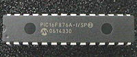
- PIC16F876A - Programmed microcontroller
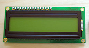
- 2x16 LCD with Green or Blue Backlight
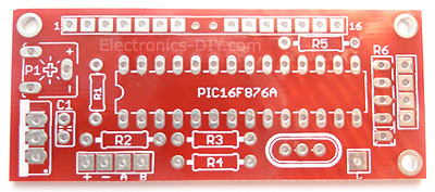
- High quality PCB with red solder mask and plated through holes
- 4MHz Resonator
- LM7805 5V Voltage Regulator
- 16x1 Gold Plated Female Header (PCB)
- 16x1 Gold Plated Male Header (LCD)
- 4x1 Gold Plated Male Header (LCD)
- 100nF Ceramic Capacitor
- 10K LCD Contrast Trimmer Potentiometer
- 4x10K Network Resistor
- 2x 100K 1% Metal Film Resistor
- 2x 6.8K 1% Metal Film Resistor
- 10 Ohm 1% Metal Film Resistor
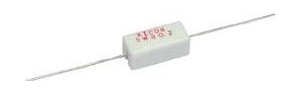
- 0.47 Ohm / 5W Power Resistor (shunt)
|
|
 Voltmeter Ammeter Description
This Voltmeter Ammeter was designed to measure output voltage of 0-70V / 0-500V with 100mV resolution and 0-10A or more current with 10mA resolution. It is a perfect addition to any DIY laboratory power supply, battery chargers and other electronic projects where voltage and current consumption must be monitored. Thanks to added calibration via SETUP, UP & DOWN buttons it is now possible to calibrate the meter to measure voltage that is higher than 70V and current that is greater than 10A.
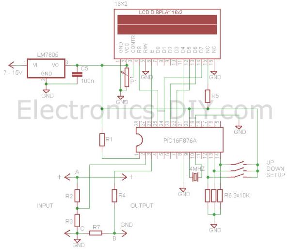
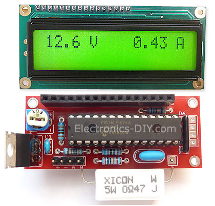
The heart of the Voltmeter Ammeter is PIC16F876A microcontroller with built-in analog to digital converters (ADC) and 2×16 green / blue backlighted LCD display.
Voltmeter Ammeter uses very few external components making it possible to fit this handy meter on a small PCB. The meter provides exeptionally accurate readings due to buit-in software based calibration and the use of 1% metal film resistors. It needs only one supply voltage that can be acquired directly from the main power supply. Entire voltmeter consumes only 10mA with LCD backlight turned on and 3mA with the backlight tuned off. LCD backlight can be turned off by disconnecting 10 Ohm resistor from the LCD display.
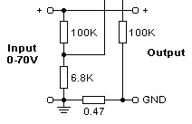
The voltage is sampled by using two connected in series 100K and 6.8K resistors.
Current sense 0.47 Ohm shunt resistor is connected in series with load at the negative voltage rail and is passed to microcontroller chip through 100K resistor.
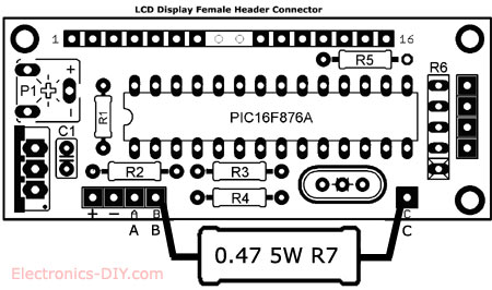
Voltmeter Ammeter PCB Layout
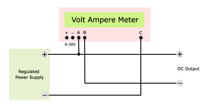
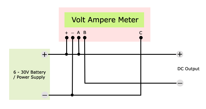
Voltmeter Ammeter Wiring Diagram
|
Measuring 6-30V battery voltage. Using single supply to measure voltage and power Volt Ammeter kit. |
Voltmeter Ammeter Calibration Process
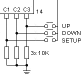
Additionally the Voltmeter Ammeter can be easlily calibrated by temporaily connecting three (SETUP, UP & DOWN) tactile buttons or even a piece of wire to C1, C2 and C3 PIC16F876 microcontroller ports.
To enter the calibration setup mode make sure the meter is powered off. Press and hold the SETUP button for two seconds while powering the meter until “Setup Mode” message is displayed on LCD display.
After “Setup Mode” message disappears we will be calibrating the voltage readings and real time voltage reading will be displayed on the display. Connect the highest voltage to Input that you will be normally measuring then connect the commercial multimeter to input as well. We will be matching the voltage of PIC voltmeter with the commercial multimeter. Use UP & DOWN buttons to match the voltage on both devices.

|
Once the voltage is matched press the SETUP button to start calibrating current readings. You can lower the voltage now and connect a load from 500mA to axpoximately 2A in series with commercial multimeter to Output of PIC multimeter. Again, we will be matching the current redings on both meters. Finally press the SETUP button again and calibrating settings will be saved in PIC16F876 microcontroller’s non-volatile EEPROM memory. Calibration process is now completed. EEPROM memory is retained even if the power supply is disconnected. Calibration only needs to be performed once. If you ever need to change the calibration settings again you can do so be following the calibration steps. The PIC multimeter is now ready to be used in the power supply or any other project of your choice. Voltmeter Ammeter Kit
|
You can purchase a complete premium quality Voltmeter Ammeter Kit at Electronics-DIY store.
Source : Voltmeter Ammeter
- What supply voltage does the Voltmeter Ammeter require?
It requires a 6V to 30V supply according to the technical specifications. - Can the meter measure voltages higher than 70V?
Yes, with calibration via SETUP, UP and DOWN buttons it is possible to calibrate the meter to measure voltages higher than 70V up to 0-500V range. - How accurate are the resistor values used for measurements?
The project uses 1% metal film resistors to provide exceptionally accurate readings. - How is current measured in this project?
Current is measured using a 0.47 Ohm shunt resistor placed in series with the load on the negative rail and fed to the microcontroller through a 100K resistor. - Does the device save calibration settings after power off?
Yes, calibration settings are saved in the PIC16F876A microcontroller's non-volatile EEPROM memory and retained after power is disconnected. - How do you enter calibration mode?
With the meter powered off, press and hold the SETUP button for two seconds while powering the meter until Setup Mode is displayed on the LCD. - What is the voltage and current resolution of the meter?
Voltage resolution is 100 mV and current resolution is 10 mA as specified. - Can the LCD backlight be turned off to save power?
Yes, the backlight can be turned off by disconnecting the 10 Ohm resistor from the LCD display.