
Summary of Seven Segment Multiplexing using PIC18F4550 Microcontroller
Seven-segment multiplexing with a PIC18F4550 lets four digits be displayed while using one port for segment lines and four pins for digit common controls, minimizing pin use. Port D carries segment lines (a–g) shared across all displays; four transistors (BC547) switch the common pins controlled by Port A. Displays are time-multiplexed rapidly so persistence of vision makes all digits appear lit. The microcontroller cycles digits, extracts individual digits from a count (0000–9999), outputs segment hex codes to Port D, and enables each digit briefly in turn.
Parts used in the Seven Segment Multiplexing with PIC18F4550:
- PIC18F4550 microcontroller
- Four common-anode or common-cathode seven-segment displays (as per circuit)
- BC547 transistors (4)
- Resistors for segment current limiting
- Resistors for transistor base (current limiting)
- Connecting wires and PCB or breadboard
- Power supply (appropriate Vcc for PIC and displays)
- Optional: decoupling capacitors and crystal/oscillator for PIC clock
As explained earlier, a seven segment interfaced with PIC uses almost an entire port (minimum 7 pins) to display a value. But a real time application, like watch, calculator etc., usually requires at least 3-4 seven segments. In such a case it is not advisable to use a port of the controller for each seven segment. In these cases, multiplexing technique is used to work with more than one seven segment. Here multiplexing of four seven-segments has been explained with PIC18F4550 to display four-digit count from 0000 to 9999.
The data pins (a-g) of all the seven-segments are connected to a single port (Port D*) as shown in the circuit diagram. Transistors BC547 are connected to COM pins of seven-segment for switching. The switching of COM pins is controlled by four pins of PortA.
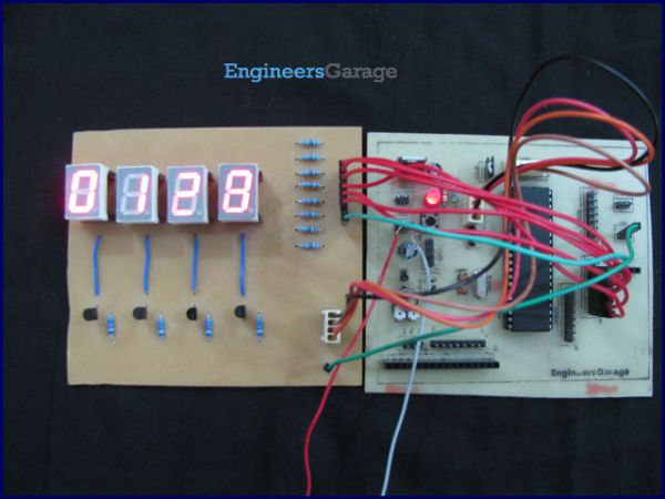
- How many port pins does multiplexing four seven-segments use?
It uses seven segment data pins on one port (Port D) plus four pins to switch the digit commons on Port A, minimizing total pins. - Can one port be shared among multiple seven-segments?
Yes, the data pins (a–g) of all seven-segments are connected to a single port and shared. - What controls switching of the common pins for each digit?
BC547 transistors are connected to the COM pins and their bases are driven by four pins of Port A to control switching. - How does multiplexing make multiple digits appear lit simultaneously?
Digits are switched on one by one with a small delay; persistence of human vision makes them appear lit together. - What is the key programming step to display a count?
Store the count, extract individual digits, send corresponding hexadecimal segment values to Port D, and enable each digit in sequence with brief delays. - What switching speed is required to avoid visible flicker?
The explanation refers to switching faster than about 25 frames per second (less than or equal to 0.04 second per frame) to avoid noticeable transitions. - Are the Port D pins contiguous for segment connection?
No, the article notes Port D pins are not continuous, so care is needed when wiring. - What digit range is demonstrated in the project?
The project displays a four-digit count from 0000 to 9999.
