Summary of PIC18F452 UART code and Proteus Simulation
This article details a UART communication project connecting a PIC18F452 microcontroller to a PC. It explains the circuit setup using a 10MHz crystal with PLL to achieve 40MHz CPU speed (10MIPS). The provided HI-TECH C code initializes UART at 9600 bps with 8-bit data, one start/stop bit, no parity, and no flow control. The complete source code and Proteus simulation are available for download.
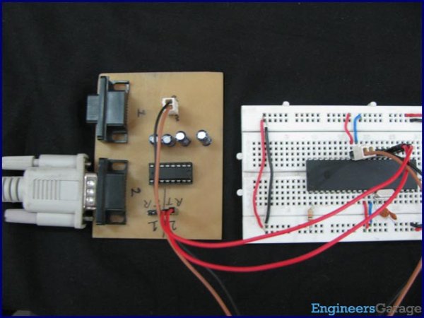
Parts used in the PIC18F452 UART Project:
- PIC18F452 Microcontroller
- 10MHz Crystal Oscillator
- Serial Adapter
- PC Computer
- MPLAB v8.76 Software
- HI-TECH C Compiler
- Proteus v7.7 Simulation Software
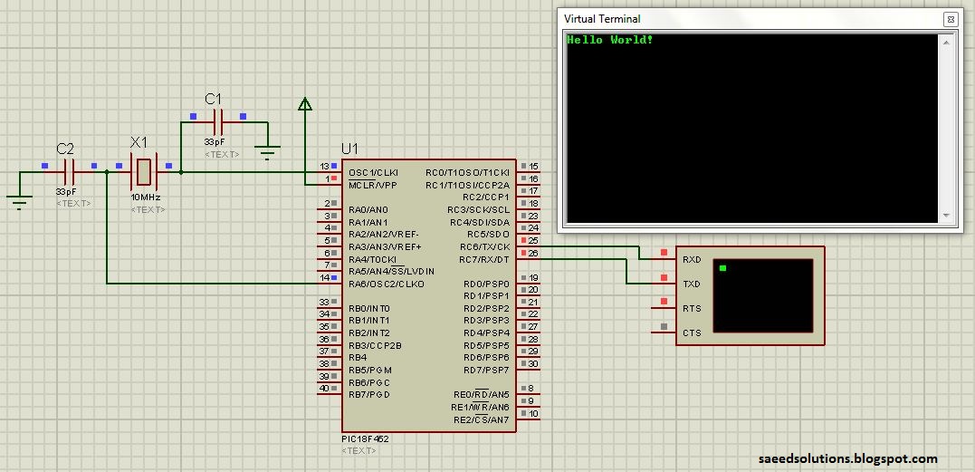
This post provides the UART code (compiled in MPLAB + HI-TECH C) for PIC18F452 (e-g to connect PIC18F452 controller with PC using serial adapter). Complete project code and the proteus simulation can be downloaded from the Downloads section at the bottom of this post. The following diagram shows the required circuit.
A crystal of 10MHz is used with PIC18F452. This crystal frequency is fed into PLL of PIC18F452, which boosts it to 40MHz. As we know that any PIC micro controller has an architecture which executes an instruction in 4 CPU cycles, hence this 10Mhz crystal + PLL makes this PIC run at 10MIPS (Million of instructions per second). The code for UART initialization is shown below.
In this function a baudrate of 9600 bps is defined (which you can easily change by changing the value from 9600 to any other number ). _XTAL_FREQ is basically the crystal frequency ( PLL output is 40MHz, which is the CPU frequency). After that different parameters of the serial port are being configured e-g the SPFRG register which is responsible for the baudrate generation for the UART. This function defines the UART to have these properties,
- Baudrate = 9600 bps
- 8 bit data mode
- 1 start and 1 stop bit
- No parity bit
- No flow control
The code for the main function is shown below.
Downloads
The code was compiled in MPLAB v8.76 with HI-TECH C and simulation was made in Proteus v7.7.
To download code and proteus simulation click here.
For more detail: PIC18F452 UART code and Proteus Simulation
- How is the PIC18F452 clock frequency determined?
A 10MHz crystal is used with the internal PLL to boost the frequency to 40MHz. - What instruction execution speed does this configuration provide?
The system runs at 10MIPS because the architecture executes an instruction in 4 CPU cycles. - Can the baud rate be changed from 9600 bps?
Yes, the baud rate can be changed by modifying the value in the initialization function. - What is the defined data mode in the UART configuration?
The code configures the UART for 8-bit data mode. - Does the UART setup include parity bits or flow control?
No, the configuration uses no parity bit and no flow control. - Which software was used to compile the code?
The code was compiled using MPLAB v8.76 with the HI-TECH C compiler. - What tool was used for the circuit simulation?
Proteus v7.7 was used to create the simulation for the project. - Where can the full project code be obtained?
The complete code and simulation files are available in the Downloads section at the bottom of the post.