
Summary of Password Based Door Lock System using 8051 Microcontroller
This article describes a password-based automatic door lock using an AT89C51 (8051) microcontroller, 4×3 keypad, LCD, relay, and DC motor. The system compares entered codes to a stored password, opens the door on a match (motor forward), waits, then reverses the motor to close; on mismatch it denies access. It covers hardware and software requirements, circuit design (power, reset, oscillator), coding and simulation steps, operation algorithm, advantages, applications, and limitations.
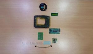
Parts used in the Password Based Door Lock System:
- AT89C51 controller
- 8051 programming board
- Programming cable
- DC battery or 12V,1A adaptor
- 4×3 matrix keypad
- 16×2 LCD
- 5V Relay
- DC motor
- BC547 Transistor
- 10k resistor (1/4 watt)
- 330 Ω resistor (1/4 watt)
- 10uF electrolytic capacitor
- 33pF capacitors (2)
- 12MHz Crystal
- Pot 10k (1/4 watt)
- Connecting wires
Traditional lock systems using mechanical lock and key mechanism are being replaced by new advanced techniques of locking system. These techniques are an integration of mechanical and electronic devices and highly intelligent. One of the prominent features of these innovative lock systems is their simplicity and high efficiency.
Here we develop an electronic code lock system using 8051 microcontroller, which provides control to the actuating the load. It is a simple embedded system with input from the keyboard and the output being actuated accordingly.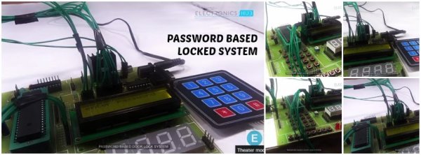
This system demonstrates a password based door lock system wherein once the correct code or password is entered, the door is opened and the concerned person is allowed access to the secured area. Again if another person arrives it will ask to enter the password. If the password is wrong then door would remain closed, denying the access to the person.
Construction and Output Video
Recommened Reading: Electronic Code Lock System using Single Transistor
Principle Behind the Circuit:
The main component in the circuit is 8051 controller. In this project 4×3 keypad is used to enter the password. The password which is entered is compared with the predefined password.
If the entered password is correct then the system opens the door by rotating door motor and displays the status of door on LCD. If the password is wrong then door is remain closed and displays “pwd is wrong” on LCD.
Circuit Diagram of Password Based Door Lock System using 8051 Microcontroller:

Password Based Door Locking System Project Required Components:
Hardware Requirements:
- at89c51 controller
- 8051 programming board
- Programming cable
- DC battery or 12V,1A adaptor
- 4×3 matrix keypad
- 16×2 LCD
- 5V Relay
- DC motor
- BC 547 Transistor
- 10k, 330 Ω resistor (1/4 watt)
- 10uF electrolytic capacitor
- 33pF capacitors – 2
- 12MHz Crystal
- Pot 10k (1/4 watt) – 1
- connecting wires
Software Requirements:
- Keil compiler
- Flash magic
- Proteus
How to Design Circuit of Password based Door Lock System?
Password based door lock circuit design uses five major components – a Microcontroller, a Relay, a DC motor, a 4×3 matrix keypad and a LCD. Here AT89C51 microcontroller is used and it is an 8-bit controller. This controller requires a supply voltage of +5V DC. In order to provide regulated 5V DC voltage to the controller we need to use 7805 power supply circuit. We can use 9V DC battery or 12V, 1A adaptor as a power source.
Reset Circuit Design:The reset pin of the microcontroller is kept active till the power supply is in the specified range and a minimum oscillation level is maintained. In other words to ensure the supply voltage does not falls below the threshold level of 1.2V and the reset pulse width is greater than 100ms (recommended for 89C51), we select the values of resistor and capacitor such that RC >=100ms. Here we select a 10K resistor and a 10uF electrolyte capacitor.
Oscillator Circuit Design: A crystal oscillator is used to provide external clock signal to the microcontroller. To ensure smooth operation, we connect two ceramic capacitors ranges from 20pF to 40pF. This crystal oscillator is connected between pin 18 and 19 of the microcontroller.
Compilation of Microcontroller Code: Once the circuit is designed and drawn on a piece of paper, the next step is to write and compile the code. Here we select the Kiel uVision software to write the program in C language.
Prior to writing the code, general steps needs to be followed like creating a new project and selecting the target device or the required microcontroller. Once the code is written, we saved it with .c extension and then added it to the source file group under the target folder. The code is then compiled by pressing F7 key.
Once the code is compiled, a hex file is created. In the next step, we use Proteus software to draw the circuit. The code is dumped into the microcontroller using an external programmer and Willar Software.
Recommend Reading: Password Based Circuit Breaker Project Circuit Diagram and Working.
Password Based Door Lock System Circuit Simulation Video
Before going to read the working of this circuit, Watch the following simulation video to get clear idea about how the above circuit works.
Password Based Door Locking System Circuit Operation
Once the circuit is powered ON, microcontroller sends commands to the LCD to display “enter password” on LCD. Now we need to enter the password using the keypad. Once password is entered, it displays 5 stars on LCD to indicate that controller read password successfully.
Now the controller compares the entered password with predefined password. If the password is matched, then the microcontroller makes P0.0 HIGH and P0.1 LOW, so the motor driver gets the input signals for forward motion of the motor.
As a result, the Door Motor rotates in forward direction to open the door. After a delay of 10seconds, the microcontroller makes P0.0 LOW and P0.1 HIGH, so the motor driver gets the input signals for reverse motion. As a result, the Door motor rotates in reverse direction to close the door.
If the password is not matched, then microcontroller maintains both P0.0 and P0.1 LOW. Hence, the door motor is stationary so that door remains closed.
NOTE: While giving the connections, make sure that there is no common connection between AC and DC supplies.
Password Based Door Lock System Algorithm
- Initially, declare the PORT1 to LCD data pins and control pins (RS and E) to P3.0 and P3.2. Also, declare PORT2 to keypad. Also use P0.0 and P0.1 for motor driver.
- Then, display the message “enter password” on LCD.
- Now read the five digit password from the user.
- Compare the entered password with the stored password.
- If password is correct, then make P0.0 pin HIGH and P0.1 pin LOW to open the door. During this time, display “Door opening” on LCD.
- After some time, make P0.0 pin LOW and P0.1 pin HIGH to close the door and after this display “Door closing” on LCD.
- If the password is wrong, then display “Wrong Password” on LCD.
- After some delay again ask to enter password.
[Also Read:Adjustable Timer With Relay Output]
Advantages of Password Based Door Lock System
- This project provides security
- Power consumption is less
- Used commonly available components
- Project is simple and easy
Applications of Password Based Door Lock System
- This simple circuit can be used at residential places to ensure better safety.
- It can be used at organizations to ensure authorized access to highly secured places.
- With a slight modification this Project can be used to control the switching of loads through password.
Limitations of Password Based Door Lock System
- It is a low range circuit, i.e. it is not possible to operate the circuit remotely.
- If you forget the password it is not possible to open the door.
- What microcontroller is used in the project?
The AT89C51 8051 microcontroller is used. - How is the user input provided?
User input is provided via a 4×3 matrix keypad. - How does the system indicate password entry on the LCD?
It displays five stars on the LCD to indicate the controller read the password. - What happens when the entered password matches the stored password?
The microcontroller makes P0.0 HIGH and P0.1 LOW to drive the motor forward to open the door, then reverses after a delay to close it. - What happens when the entered password is wrong?
The microcontroller keeps P0.0 and P0.1 LOW so the door motor remains stationary and displays Wrong Password on the LCD. - What power supply is recommended for the controller?
A regulated 5V DC supply is required, typically from a 7805 regulator fed by a 9V battery or 12V,1A adapter. - Which software tools are used for coding and simulation?
Keil uVision is used to write and compile code, Flash Magic for programming, and Proteus for simulation. - How is the reset circuit designed for the 89C51?
Reset uses an RC such that RC >= 100ms; the article selects a 10k resistor and 10uF capacitor. - What components form the oscillator circuit?
A 12MHz crystal with two ceramic capacitors (20pF to 40pF range) connected between pins 18 and 19 form the oscillator. - What are the main advantages of this project?
It provides security, low power consumption, uses commonly available components, and is simple to build.
