
Summary of Digital Count Down Timer using PIC Microcontroller
Summary: Mithun developed a 0–99 minute digital countdown timer using a PIC16F628A, 4 MHz crystal, LCD display, relay, and pushbuttons. The project includes circuit diagrams, full source code in mikroC, and breadboard photos. Users set minutes via Units and Tens buttons and start/stop with a single button; the software validates inputs and uses the MCU timer unit to implement accurate countdown and relay control.
Parts used in the Digital Count Down Timer:
- PIC16F628A microcontroller
- 4 MHz external crystal
- Character LCD module
- Relay
- Push button switches (Start/Stop, Units, Tens)
- Resistors (for buttons and relay drive)
- Transistor (for driving relay)
- Breadboard and jumper wires
- Power supply (suitable for PIC and relay)
- Proteus for circuit simulation (optional but used in article)
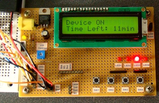
In this article, our author Mithun has developed a 0 – 99 min counter using PIC microcontroller 16F628A. So basically this is a digital count down timer ideal for engineering and diploma students for their project requirements. We have given complete circuit diagram of the digital count down timer along with full source code. In addition, photographs of the breadboard setup is uploaded.
Every micro controller has a timer unit inside. A timer is nothing more than a time counting device fabricated inside the micro controller unit. A wide range of practical applications require a timer in action.
 For example, we need to turn a motor ON for 5 minutes and then turn it OFF as part of a particular project; how will we do that? A timer inside a mircocontroller unit aids us in implementing this perfectly. A timer can be used to count the 5 minutes exactly and the bits that get SET at 5 minutes limit can be used to program the controller to turn OFF some device(s).
I hope you got a basic idea about timer unit and its practical applications. We are going to make this project using an LCD display, PIC controller 16F628A and a 4 MHz external crystal to provide the necessary clock. We will be writing the codes using micro C.
In any project that involves an LCD, the first step is to initialize the LCD module. We have written detailed articles about interfacing LCD to an MCU before. You can learn more about Interfacing an LCD to 8051 and Interfacing LCD module to AVR controller in these articles. If you want to learn more about character LCD displays in detail, this tutorial on Character LCD displays will be of help.
Now, we need to configure relay and switches. The code snippet for the same is given below.
Here ‘sbit’ stands for set bit. You can do the same another way using “#define” command. This line means that RA3 pin will be known as the Relay/ RB0 pin will be known as etc.
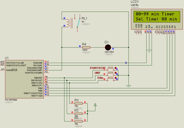
Even though the project name “digital count down timer” sounds so silly, its operation is not that simple. We have given below a proteus diagram of the circuit to explain the project perfectly.
Analyzing the circuit diagram, you can see three buttons . One button is for Start/Stop function and the other 2 buttons for Units & Tens counting. We will configure our LCD module with display messages corresponding to the button configurations
These are the messages we will be showing in our LCD. To control the system we’ll need some other variables as well. These variables are declared in the code snippet given below.
 Lets understand the counting mechanism now. The circuit is wired in such a way that, the user will have to select the limit of counting initially. If the user is interested in counting 1 to 9 minutes only, then he is supposed to press the units button alone. If he is interested in counting 1 to 99 minutes, then he should press the Tens button along with Units button. Once he sets the limit, he should press the Start/Stop button to start the timer (its a push button switch and same button switch is used to stop the timer as well).
Note:- Since the timer operation depends upon the value selected by user (units and tens switch), we have to check certain possible error conditions before starting the timer. Assume a condition in which the user forgot to select units or tens switch and pressed the start/stop button directly; what is supposed to happen in this scenario? It’s an expected error condition that should be handled inside the software. A common way to handle this scenario is to start the timer only if the limit value is greater than zero. The code snippet given below handles this condition.
For more detail: Digital Count Down Timer using PIC Microcontroller
- What microcontroller is used in the project?
The project uses the PIC16F628A microcontroller. - What clock source is used for the PIC?
A 4 MHz external crystal is used to provide the necessary clock. - How does the user set the countdown limit?
The user sets the limit using Units and Tens pushbuttons; Units alone for 1–9 minutes, Units plus Tens for 1–99 minutes. - Which button starts and stops the timer?
A single Start/Stop pushbutton is used to both start and stop the timer. - How does the software handle no selection of Units or Tens before starting?
The code checks that the selected limit value is greater than zero and starts the timer only if it is, handling the error condition. - What language/tool is used to write the code?
The source code is written using mikroC (micro C). - What display is used to show messages and status?
A character LCD module is used to display messages corresponding to button configurations and status. - How is the relay controlled in the project?
The relay is controlled via a designated PIC output pin (mapped using sbit or #define) and driven through appropriate transistor/resistor circuitry as shown in the circuit diagram. - Is there a simulation or diagram provided?
The article provides a Proteus circuit diagram to explain the project.
