Summary of Interfacing LCD with PIC Microcontroller – CCS C
This tutorial explains interfacing a 16×2 HD44780-compatible character LCD with a PIC16F877A using the CCS C compiler. It compares 4-bit and 8-bit modes, recommends 4-bit for pin saving, and shows how to use CCS C’s lcd.c library. It details required signal pins, two ways to define pin mappings (PORT access or individual PIN access), and lists key library functions (lcd_init, lcd_putc, lcd_gotoxy, lcd_getc, lcd_cursor_on) plus special backslash commands for control.
Parts used in the Interfacing 16x2 LCD with PIC16F877A:
- PIC16F877A microcontroller
- 16×2 character LCD module (HD44780 compatible)
- Power supply for PIC and LCD (Vcc, GND)
- Potentiometer for LCD contrast (optional but typical)
- Connecting wires/jumpers
- Breadboard or PCB for mounting
- CCS C Compiler with lcd.c library
In this tutorial we will see How to interface a 16×2 character LCD Module with PIC 16F877A Microcontroller using CCS C Compiler. 16×2 character LCD is a very commonly used LCD module in electronic projects and products. 16×2 means it can display 2 rows of 16 characters. It is a very basic and low cost module. Its other variants such as 16×1, 20×4 are available in the market. In these displays each character is displayed using 5×8 or 5×10 dot matrix. These LCDs commonly uses HD44780 compliant controllers for their operation.
Interface between a microcontroller and LCD can be 4-bit or 8-bit. The difference between 4-bit and 8-bit is how data are send to the LCD. To write an 8-bit character to the LCD module in 8-bit mode, ASCII data is send through the data lines DB0- DB7 and data strobe is given through the E line.
 But 4-bit mode uses only 4 data lines. In this mode the 8-bit ASCII data is divided into 2 parts which are send sequentially through data lines DB4 – DB7 with its own data strobe through the E line. The idea of 4-bit communication is to save as much pins that used to interface with LCD. The 4-bit communication is a bit slower when compared to 8-bit. The speed difference is only minimal, as LCDs are slow speed devices the tiny speed difference between these two modes is not significant. Remember that our microcontrollers works in the speed of MHz range. Thus the 4-bit mode data transmission is most commonly used.
CCS C provides a built in library file, “lcd.c” for interfacing LCDs having HD44780 compliant controllers using 4-bit mode communication. Just include this file in your program and enjoy.
CCS C LCD Library
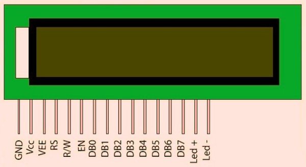
LCD Connections
For the proper functioning of LCD Library, you should define the connections of below 7 pins used for LCD interfacing in the program.
- Enable – E or EN
- Register Select – RS
- Read / Write – RW
- Data 4 – DB4 or D4
- Data 5 – DB5 or D5
- Data 6 – DB6 or D6
- Data 7 – DB7 or D7
These must be defined before including the header file, it can be done in two ways as given below.
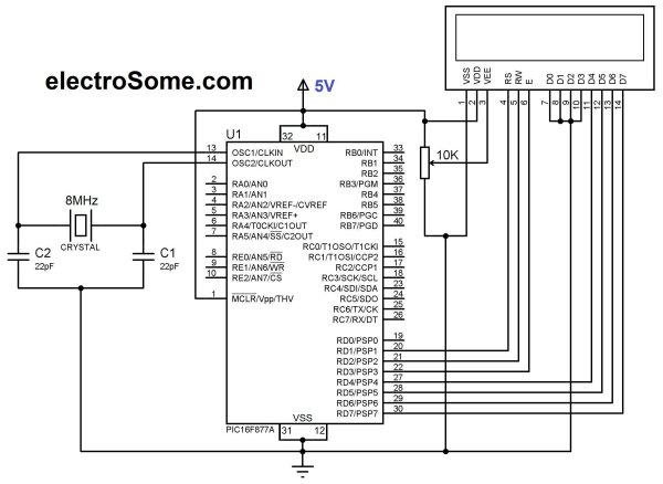
PORT Access Method
This method requires the entire 7 bit interface connected to same GPIO port. It should be defined before including the header file as shown below.
#define LCD_DATA_PORT getenv("SFR:PORTD")
This defines that the entire 7 bit interface is connected to PORTD of PIC Microcontroller.
PIN Access Method
In this method you can connect those 7 bits to any GPIO pins and it should be defined before including the header file as shown below.
//LCD Module Connections
#define LCD_RS_PIN PIN_D1
#define LCD_RW_PIN PIN_D2
#define LCD_ENABLE_PIN PIN_D3
#define LCD_DATA4 PIN_D4
#define LCD_DATA5 PIN_D5
#define LCD_DATA6 PIN_D6
#define LCD_DATA7 PIN_D7
//End LCD Module Connections
Important Functions
lcd_init()
This function must be called before any other lcd functions. It initializes the LCD module with above defined connections.
 lcd_putc(c)
This function will display c on the next cursor position of the LCD. You can print strings and characters using this function. You can also use following backslash character constants for sending different commands to LCD.
- \\a – To set cursor to the upper left
- \\f – To clear display and set cursor to upper left
- \\n – To go to start of next line
- \\b – To move back one position
lcd_gotoxy(x, y)
This function can be used to set cursor position of the LCD, upper left position is (1,1).
lcd_getc(x, y)
This function returns the character at the position (x, y) on the LCD.
lcd_cursor_on(int1 on)
This function can be used to turn the cursor on or off.
Example :
lcd_cursor_on(TRUE); //Turns ON the cursor
lcd_cursor_on(FALSE); //Turns OFF the cursor
Note : For more details you can read the library file “lcd.c” in the location C:/Program Files/PICC/Drivers/.
For more detail: Interfacing LCD with PIC Microcontroller – CCS C
- What does 16×2 mean in the LCD module?
It means the LCD can display 2 rows of 16 characters each. - Can I interface the LCD in 4-bit mode?
Yes, the tutorial recommends 4-bit mode to save microcontroller pins and CCS C lcd.c supports it. - How is 8-bit data sent to the LCD?
In 8-bit mode ASCII data is sent through DB0–DB7 and strobed via the E line. - How is 4-bit data communication done?
In 4-bit mode each 8-bit byte is split into two 4-bit nibbles sent sequentially via DB4–DB7 with E strobes. - What pins must be defined for the CCS C LCD library?
Enable (E), Register Select (RS), Read/Write (RW), Data4 (DB4), Data5 (DB5), Data6 (DB6), Data7 (DB7). - How do I define the LCD connections using PORT access?
Define the data port before including the header, for example #define LCD_DATA_PORT getenv(SFR:PORTD). - How do I define the LCD connections using PIN access?
Define each signal pin before including the header, for example #define LCD_RS_PIN PIN_D1 and similarly for other pins. - Which function initializes the LCD library?
lcd_init() must be called before any other lcd functions. - How can I print characters and strings to the LCD?
Use lcd_putc(c) to display a character at the next cursor position; it supports backslash constants like \n and \f. - How do I turn the LCD cursor on or off?
Use lcd_cursor_on(TRUE) to turn on and lcd_cursor_on(FALSE) to turn off the cursor.