Summary of Digital Ammeter circuit using pic microcontroller
This project builds a low-cost, microcontroller-free digital voltmeter using the ICL7107 ADC/driver, driving four common-anode 7-segment displays. The ICL7107 provides ADC, display drivers, clock, and reference functions; a 7805 supplies regulated 5V and a 555 configured as an astable generates the negative supply required by PIN 26. Components set the ADC clock, filter the reference, select measurement range, and allow calibration for accurate voltage readings.
Parts used in the Electronic Voltmeter:
- ICL7107 (IC7107)
- LM555 timer IC
- PCB (Wellpcb.com)
- LM7805 voltage regulator
- Common anode 7-segment LED display (Quantity: 4)
- Terminal Block 2 pin (2)
- 47k resistor
- 1k resistors (5)
- 22k resistor
- 10k resistor
- 120k resistor
- Potentiometer 5K (RV1)
- 100nF capacitors (3)
- 10uF capacitors (2)
- 100pF capacitor
- 220nF capacitor
- 47nF capacitor
- Power supply 9V/12V
- Berg sticks (2)
- 40 pin IC base
- 8 pin IC base
- Probe or wire
- 1N4148 diodes (2)

In this project we have a tendency to design a circuit to build an electronic voltmeter while not making use of any microcontroller. Here we have a tendency to employing a very moderate IC for voltage activity particularly ICL7107/CS7107. Making use of ICL7107, we are able to build correct and really low price digital voltage measurement meter. ICL7107 may be a 3.5 digit analog to digital device (ADC) that consumes extremely low power. The IC has internal circuit for driving four seven section show to show the measured voltage. It additionally encompasses a clock circuit and a reference voltage supply.
Step 1: Requirements of Components
- IC7107
- LM555
- PCB (Wellpcb.com)
- LM7805
- Common anode 7 segment LED display (Quantity: 4)
- Terminal Block 2 pin (2)
- 47k
- 1k (5)
- 22k
- 10K
- 120K
- Pot 5K
- 100nF (3)
- 10uF (2)
- 100pF
- 220nF
- 47nF
- Power Supply 9v/12v
- Berg sticks (2)
- 40 pin IC base
- 8 pin IC base
- Probe or wire
- 1N4148 diode (2)
Step 2: Circuit Diagram and Working Explanation
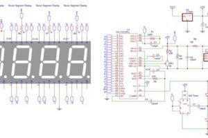
Working of this electronic voltmeter Circuit is extremely straightforward. ADC within the IC is desegregation device or twin kind Analog to digital device. Internal ADC of this IC reads the voltage that to be measured and compare it with an indoor reference voltage and converts that into the digital equivalent. Then this digital equivalent is decoded for seven section Displays by driver circuit within ICL7107 and so showed over four seven segments diode display.
Here electrical device R1 and electrical capacitor C1 area unit won’t to set the frequency of internal clock of ICL7107. Electrical capacitor C2 filters the fluctuations in internal reference voltage and provides stable reading on seven phase displays. R5 is to blame for dominant the variations of the meter. (R5=1K for 0-20V vary and 10K for 0-200V range). RV1 could be a potentiometer which can be used for calibrating the voltage of meter or may be set the reference voltage for internal ADC.
This circuit includes four Common Anode Seven phase light-emitting diode Displays with a negative voltage indicator. This circuit ought to be operated at 5V voltage offer, that’s why we’ve got used a 7805 transformer IC to provide 5v to the circuit still as for preventing the injury of ICL7107. Negative Voltage Supply: Here we’ve got conjointly have to be compelled to offer negative power to PIN twenty six of the ICL7107, that we’ve got used 555 IC. The 555IC timer IC is designed here as ASTABLE multi-vibrator. The electrical device here may be modified but the choice ought to pursue for optimum negative voltage. If hand-picked capacitance doesn’t suit well, then we have a tendency to can’t get most negative voltage at the output. Here we’ve got used 100nF and 10uF.
- What IC is used for the ADC and display driving in this voltmeter?
The ICL7107 analog to digital converter is used; it includes internal display drivers for four seven segment displays. - Can this voltmeter be built without a microcontroller?
Yes, the design intentionally avoids microcontrollers by using the ICL7107 and supporting analog circuitry. - How is the required negative supply for PIN 26 of the ICL7107 generated?
A 555 IC configured as an astable multivibrator is used to generate the negative voltage supply for PIN 26. - What provides the 5V supply to the ICL7107 circuit?
An LM7805 voltage regulator is used to provide the 5V supply to the circuit. - Which components set the ICL7107 internal clock frequency?
A resistor R1 and capacitor C1 are used to set the frequency of the internal clock of the ICL7107. - How is the reference voltage stabilized for accurate readings?
A capacitor C2 filters fluctuations in the internal reference voltage to provide stable display readings. - How do you change the measurement range of the meter?
The resistor R5 selects the range: R5 = 1K for 0-20V range and R5 = 10K for 0-200V range. - What is the purpose of the potentiometer RV1?
RV1 is used for calibrating the meter by adjusting the reference voltage for the internal ADC. - Are specific capacitances required for the negative voltage generator?
Yes, the capacitances in the 555 circuit must be chosen for optimal negative voltage; the article mentions using 100nF and 10uF. - What type of displays does the circuit use?
The circuit uses four common anode seven segment LED displays with a negative voltage indicator.