Summary of BATTERY CHARACTERIZER using PIC18F252
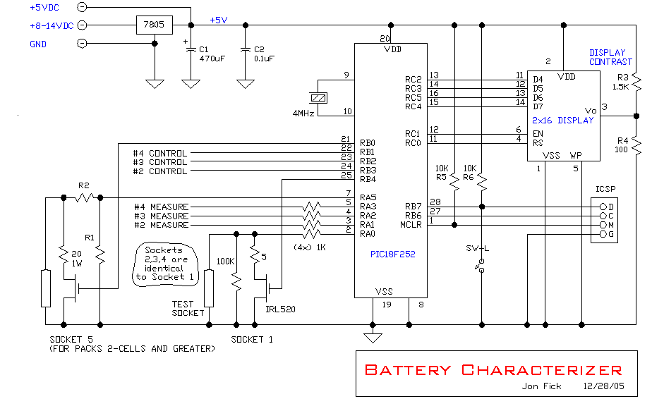
This article describes a PIC18F252-based battery characterizer for NiCd/NiMH cells that applies a ~200 mA (~0.1C) fixed load, measures mAh capacity, and estimates internal resistance. It supports up to five sockets (socket 5 for packs), samples once per minute, auto-stops at per-cell 1.0 V cutoff, and displays results on an LCD with two pushbuttons. Source code, wiring, and configuration constants for resistances, timing, and ADC channels are provided.
Parts used in the Battery Characterizer:
- PIC18F252 microcontroller
- 16 MHz crystal (example shows 4 MHz configured)
- LCD display (HD44780-style parallel)
- 20K potentiometer (LCD contrast)
- FETs for load switching (5 load FETs)
- Load resistors (LOAD_0..LOAD_4 values, e.g., 4.9 ohm and 19.5 ohm)
- Resistors R1 (5350 ohms) and R2 (10220 ohms) for channel 5 scaling
- Pushbutton (SW 1 / BUTTON on B7)
- Battery sockets (up to five, socket 5 for multi-cell packs)
- 8–16 VDC power supply
- Bypass and decoupling capacitors (implied for microcontroller and LCD)
- PCB or protoboard and wiring/connectors
Introduction
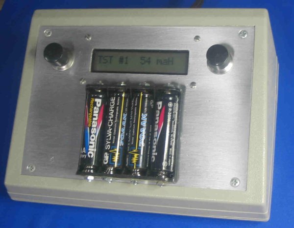
This circuit is a battery characterizer that applies a fixed load to a charged NiCad or NiMH cell and measures milliamp-hour capacity as it discharges.
There is no single load that can be applied to a battery to measure milliamp-hours. It depends on the battery type, it’s intended application, etc. This device is simply one methodology that gives me a relative idea of the performance of NiCad and NiMH batteries in my drawer. Discharge is approximately 200mA which is approximately 0.1C for AA size cells or packs constructed with AA size cells.
When NuMH¹ batteries come into being, I’ll update this device to handle those too.
Features
- Up to five cells can be characterized at one time
- To avoid total discharge the load is disconnected when test stops
- Determines internal resistance and accumulated milliamp-hours.
Specifications
- Power: 8-16VDC at ~100mA
- Sampling: once per minute
- Load 0.1C (~200mA)
Operation
Connect an 8-16VDC power supply to the battery characterizer.
Insert the cell(s) or connect the battery pack to be tested. After a charged cell is inserted in a socket, the unit waits for the voltage to stabilize (to avoid false measurements during first contact,) then the internal resistance is measured for later display when the cell test is complete. Thereafter, the cell is placed in TEST mode, the load is turned on, and milliamp-hours are accumulated. When the cell voltage falls below the cutoff voltage (1.0V per cell,) TEST mode is terminated and the load is turned off. DONE mode thereafter displays the total milliamp-hours and starting internal resistance until the cell is removed from the socket.
Socket #5 is designed for multiple-cell packs. The number of cells is calculated from the initial measured charged voltage and is in turn used to calculate the proper cutoff voltage by dividing by the nominal 1.2V per-cell voltage.
Code:
/****************************************************************************
BCHAR18.C

This is a battery characterizer for NiMH and NiCD cells.
Four 5V ADC inputs (1.2V cells) and one 8V input (3.6 or 4.8V cells) collect samples.
Control and display is done via two pushbuttons and an LCD display.
Menus and results are viewed on the display.

WORKING CODE

Next:
    put in overvoltage sense

                   ---------
           +5--20-|Vdd      |
           +5---1-|Mclr     |
          Gnd---8-|Vss      |
          Gnd--19-|Vss      |
         4MHz--10-|Xtal     |
         4MHz---9-|Xtal     |
                  |         |
                  |         |
     SOCKET 1 --2-|AN0    B4|-24----load 0 FET gate
     SOCKET 2 --3-|AN1    B3|-24----load 1 FET gate
     SOCKET 3 --4-|AN2    B2|-23----load 2 FET gate
     SOCKET 4 --5-|AN3    B1|-22----load 3 FET gate
     SOCKET 5 --7-|AN4    B0|-21----load 4 FET gate
                  |         |
      SW 1 ----28-|B7       |
                  |         |
                  |         |         ---------
                  |       C2|-13--11-|D4       |
                  |       C3|-14--12-|D5       |
                  |       C5|-16--13-|D6       |
                  |       C4|-15--14-|D7       |
                  |         |        |         |-3--20K pot (contrast)
                  |       C1|-12---6-|EN       |
                  |       C0|-11---4-|RS       |
                  |         |        |         |
                  |         |   +5-2-|         |
                  |         |  Gnd-1-|         |
                  | 18F252  |  Gnd-5-|         |
                  |         |        | DISPLAY |
                   ---------          ---------

*/

#include < 18f252.h >
#device *=16 ADC=10    /* allow RAM addresses over 255 */
#include < jonsinc.h >
#fuses XT, NOPROTECT, NOOSCSEN, BROWNOUT, NOWDT, BORV20, PUT, NOSTVREN, NODEBUG, NOLVP, NOWRT, NOWRTD, NOWRTB

//=============================================================
// crystal frequency (Hz)
#define CRYSTAL_FREQ         4000000
// actual power supply voltage (volts)
#define VDD                  5.02
// cell nominal voltage (volts)
#define CELL_NOM_VOLTAGE     1.2
// voltage at which mAh accumlation stops (volts)
#define CUTOFF_VOLTAGE       1.0
// actual load resistances (ohms)
#define LOAD_0_OHMS          4.9
#define LOAD_1_OHMS          4.9
#define LOAD_2_OHMS          4.9
#define LOAD_3_OHMS          4.9
#define LOAD_4_OHMS          19.5
// actual FET RDS(on) resistance (ohms)
#define FET_RDS_OHMS         0.17
// actual scaling resistors R1 and R2 for channel 5 (ohms)
#define R1                   5350
#define R2                   10220
// display time for logo screens (normally 750 mS)
#define LOGO_TIME            750
// wait time for which voltage is displayed after a cell is inserted into a socket (seconds)
#define INITIAL_DELAY        2
// wait time after which display goes into rolling status mode (seconds)
#define STATUS_DELAY         10
// screen cycle time when in rolling status mode (seconds)
#define SCREEN_CYCLE_DELAY   2
// screen cycle time when in cell detail mode (mS)
#define DETAIL_CYCLE_DELAY   1500
// restart IRQ timer at adjusted value for 1-second accuracy (0-255, higher makes shorter IRQ tick)
#define IRQ_RESTART_TICK     3
// time at cutoff voltage required to end test (seconds, normally 60)
#define AUTOSTOP_TIME        60
// button time after which unit will display cell details (31mS interrupt counts, normally 16, ~= 0.5 second)
#define BUTTON_DETAIL_TIME   16
// button time after which unit will reset (31mS interrupt counts, normally 128, ~= 4 seconds)
#define BUTTON_RESET_TIME    128
// round to nearest 10's or 100's
#define ROUNDNUM             100
// socket definitions
#define SOCKET_1             0
#define SOCKET_5             4
// overvoltage definitions
#define CH_1_4_OVERVOLTAGE   2.0
#define CH_5_OVERVOLTAGE     6.0
//=============================================================

// LCD STUFF
#define LCD_D0      PIN_C2
#define LCD_D1      PIN_C3
#define LCD_D2      PIN_C5
#define LCD_D3      PIN_C4
#define LCD_EN      PIN_C1
#define LCD_RS      PIN_C0
#define LOAD_0      PIN_B4
#define LOAD_1      PIN_B3
#define LOAD_2      PIN_B2
#define LOAD_3      PIN_B1
#define LOAD_4      PIN_B0
#define BUTTON      PIN_B7
#define OHM_SYM     0xF4
#define FIRST_LINE  0
#define CLEAR_DISP  0x01
#define CELL_STATE_READY        'R'
#define CELL_STATE_TEST         'T'
#define CELL_STATE_DONE         'D'
#define FMULT                   ( float ) R1 / ( float ) ( R1 + R2 )
// sample interval is normally 60 seconds
#define SAMPLE_INTERVAL_SEC    60

#use delay ( clock=CRYSTAL_FREQ )
#use standard_io ( A )
#use standard_io ( B )
#use standard_io ( C )

separate void DelayMs ( long cDelay );    // prototype statements
separate long Round ( float fNum, int cNearest );
float ReadAdc ( unsigned int cChannel );
void LoadControl ( char cChannel, char cState );
void LCD_Init ( void );
void LCD_SetPosition ( unsigned int cX );
void LCD_PutChar ( unsigned int cX );
void LCD_PutCmd ( unsigned int cX );
void LCD_PulseEnable ( void );
void LCD_SetData ( unsigned int cX );

static char cCellDetailWanted, cSwitchCount, cInitialDelayCount;
static char cInterruptCount1s, cInterruptScreenCycleCount;
static long iInterruptStatusCount, iRunMinutes [ 5 ];
static char cSocket, cSocketDisp, cY, cSkip, cStatusMode;
static char cLogging [ 5 ], cAutoStopCount [ 5 ], cCellCount [ 5 ];
static char cSampleCount [ 5 ], cCellPresent [ 5 ];
static char cSocketState [ 5 ], cSampleFlag [ 5 ], cIntResCount [ 5 ];
static float fIntRes [ 5 ], fLoadRes [ 5 ], fAccumMa [ 5 ];
static float fCutoffVoltage [ 5 ], fMultiplier [ 5 ], fOverVoltage [ 5 ];
static float fStartVoltageUnloaded [ 5 ], fStartVoltageLoaded [ 5 ];
static float fPresentVoltage [ 5 ];

//************************************************************************
For more detail: BATTERY CHARACTERIZER using PIC18F252
- What battery types does this characterizer support?
It supports NiCd and NiMH cells and packs as described in the article. - How many cells can be tested at once?
Up to five cells can be characterized at one time. - What load does the device apply during discharge?
The discharge load is approximately 200 mA, about 0.1C for AA-size cells. - When does the test stop automatically?
The test stops when cell voltage falls below the cutoff voltage of 1.0 V per cell, with an autostop time of 60 seconds at cutoff. - How often are voltage samples taken?
Sampling is performed once per minute (60 seconds). - How is socket 5 handled differently?
Socket 5 is designed for multiple-cell packs; the number of cells is calculated from initial charged voltage to set the proper cutoff voltage. - How is internal resistance measured and displayed?
Internal resistance is measured after voltage stabilizes when a charged cell is inserted and is retained for display when the test is complete. - What power supply is required?
The unit requires an 8–16 VDC power supply at about 100 mA. - How does the device avoid total discharge?
To avoid total discharge, the load is disconnected when the test stops. - What microcontroller signals control the loads and ADC inputs?
The PIC18F252 uses AN0–AN4 for ADC inputs and PORTB pins B0–B4 to drive the load FET gates.