Summary of Metal detector robot using pic microcontroller
This project implements a single-frequency detector using an 8‑pin PIC12F683 microcontroller plus a few passive components. The PIC samples an AC input (AC‑coupled and biased to midrail), runs a digital signal processing algorithm to detect a selected tone, and drives an output high when the tone exceeds a user set threshold. Code (HEX and ASM) is provided, and frequency and threshold are set via voltage dividers. The circuit is suitable for remote control, note detection, or tone sensing in noisy signals.
Parts used in the Single Frequency Detector:
- PIC12F683 microcontroller (U1)
- Regulated 5V supply (eg. LM7805 regulator output)
- Resistor R1 (part of input bias divider)
- Resistor R2 (part of input bias divider)
- Capacitor C1 (AC coupling capacitor)
- Resistor R3 (frequency select divider)
- Resistor R4 (frequency select divider)
- Resistor R5 (detection threshold divider)
- Resistor R6 (detection threshold divider)
- Decoupling capacitor C2
- Programmer for PIC microcontrollers
- Breadboard or PCB and wiring
This project describes hardware and software I have developed which allows a small 8 bit PIC microprocessor to function as a single frequency detector or tone decoder.
Such a circuit can be used to detect the presence of a certain frequency within an analog signal, such as an audio signal. I could be used in remote control applications, or to detect musical notes, or for any other situation where a specific frequency must be detected in a signal that may contain other frequencies or noise.
The circuit is based an 8 pin PIC 12F683 microprocessor. Only a few additional resistors and capacitors are needed to complete a circuit that will accept an analog signal and drive a microprocessor output pin high when the selected frequency is present in the signal. The circuit can be used as a frequecy detector IC that is part of some larger circuit of the users design.
The steps that follow detail the operation of the circuit and the program that runs on the processor. A description of the digital signal processing algorithm used by the PIC is included, but it is not necessary to understand it to make use of this circuit.
The code for programming the processor is included as a *.hex file. The source code *.asm file is also provided, to allow a user that is familiar with the Microchip PIC assembly language to modify the program. These files can be found under the step titled “Source Code”.
The operation of the circuit and the function of each component is described in the section that covers the schematic.
Step 1: Parts and Tools
This circuit can easily be built on a solder less breadboard. The components are widely available at low cost from a number of sources, such as DigiKey, Mouser, Jameco, etc. that you may already be familiar with if you work with electronics.
You will need a programmer for PIC microprocessors. I have seen instructions on this site for building your own programming device, but I cannot speak for any of them. The programmer I use is from a company called Micro Engineer Labs, Inc. at http://www.melabs.com.
It is also handy to have an audio generator of some sort, for testing and experimentation. This can be as simple as a connection to the line out of a PC, CD player, MP3 player, etc.
For example, to verify that the circuit works to detect a certain frequency, just play a file containing that frequency, with the audio output of the playback device connected to the input of the circuit.
A useful program for generating sound files can be downloaded for free at http://www.goldwave.com. This program allows you to create *.wav files containing specific tones, sweeps, etc. very easily.
Step 2: Schematic and Circuit Description
The programmed PIC microprocessor (U1) is used in the circuit as shown in the schematic.
The connection labeled +5V must connect to a regulated 5V power supply, such as the output of LM7805 regulator circuit.
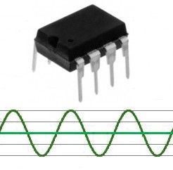
The A/D converter measures voltages between 0V and the supply voltage VDD, which is usually 5 volts. The analog input may be a signal that swings above and below 0 volts, so its waveform will have positive and negative portions. In order to sample the input waveform with the A/D converter, the input signal needs to be shifted. The voltage divider created by resistors R1 and R2 sets the bias at half of the 0 to VDD A/D input range. The capacitor C1 couples the AC input signal to the A/D input, so now the input waveform swings about ½ VDD instead of swinging about 0 volts, as shown in the graphs below.
R3 and R4 form a voltage divider used to set the target frequency. The processor reads the voltage at the frequency select pin and uses the value to determine the correct coefficients needed by the algorithm to determine if the target frequency is present.
R5 and R6 form a voltage divider used to set detection threshold. This allows the user to select the magnitude of the algorithm output that is necessary to make the program turn the output HIGH. The processor reads the voltage at the detection threshold pin and uses the value to determine the detection threshold.
C2 is a decoupling capacitor used with the microprocessor to keep the VDD supply free of spikes.
- What microcontroller does the project use?
The project uses an 8 pin PIC12F683 microcontroller. - Can the circuit detect a single frequency in a noisy signal?
Yes, the PIC runs a digital algorithm to detect a selected tone even among other frequencies or noise. - How is the analog input prepared for the PIC A/D converter?
The input is AC coupled with C1 and biased to half VDD using resistors R1 and R2 so the A/D can sample it. - How is the target frequency selected?
The processor reads a voltage set by the R3 and R4 voltage divider to determine the coefficients for the detection algorithm. - How is the detection threshold set?
The processor reads a voltage from the R5 and R6 voltage divider to determine the magnitude required to trigger the output. - What output behavior indicates detection?
The microprocessor drives an output pin high when the selected frequency is present and exceeds the threshold. - Are the program files provided?
Yes, the HEX programming file and the ASM source code are provided under the Source Code section. - What power supply is required?
The circuit requires a regulated 5V supply, for example the output of an LM7805 regulator. - What tools are useful for testing?
An audio generator or the line out from a PC, plus a PIC programmer, are useful for testing and verification.