
Summary of PIC12F675 Tutorial 6 : Driving a standard servo motor with a PIC
Summary: This tutorial explains using a PIC12F675 microcontroller to drive a standard servo (e.g., Futaba) by generating 20 ms repeated pulses via Timer 0 interrupts. Pulse widths (1.0 ms, 1.5 ms, 2.0 ms) set positions (+45°, center, -45°). The internal 4 MHz clock with Fosc/4 provides a 1 MHz Timer 0 clock; prescaler and Timer 0 create the 20 ms timebase. The example cycles predefined positions at one-second intervals, holding center for two seconds. Minimal hardware is needed: a servo control line, power, decoupling caps, and ICSP for programming.
Parts used in the Servo Motor project:
- PIC12F675 microcontroller
- Standard servo motor (e.g., Futaba)
- Solderless breadboard or plugblock
- Power supply for servo and PIC
- Decoupling capacitors
- ICSP connection/programmer
- Optional LM35DZ temperature sensor (not used)
- Optional LED (not used)
- Optional MAX232CPC (not used)
Servo motor driver tutorial. This tutorial uses the 12F675 microcontroller to drive a servo.
The microcontroller generates the signals to control a standard servo using Timer 0 interrupts (I used a Futaba servo). It does not do anything clever just sets the servo position to predefined positions at one second intervals.
A Timer 0 interrupt creates the 20ms timebase for servo updates using the internal clock and prescaler to accurately set the interrupt repeat rate.
Surprisingly servos are absolutely simple to control all the hard work is done for you (in the internals of the servo itself). All you need to do is generate a pulse signal repeated at every 20ms (approx).
You need to generate a pulse of the correct time as this determines the servo’s position. A pulse high signal of duration of 1.5ms sets the servo motor position to the center or zero degrees.
| Pulse width | Servo motor position |
| 1.0ms | +45° (clockwise rotation) |
| 1.5ms | zero position |
| 2.0ms | -45° (anti clockwise) |
Note: These are the normal settings acceptable to most servo motors and the software is capable of going outside these ranges but you have to check that your servo is capable of doing this. If the servo hits the end stop then it is not capable and larger current will be drawn and the servo will eventually damage itself.
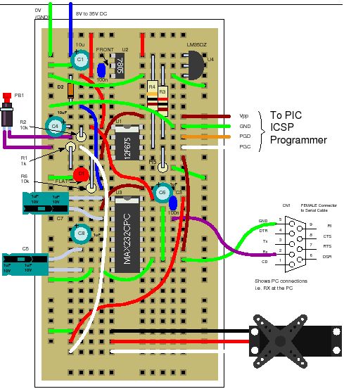
Solderless breadboard
The circuit uses the same plugblock as before but most of the components are not used – all you really need is the ICSP connection and the servo connection, power supply and decoupling capacitors. The LM35DZ, LED and MAX232CPC are not used. If you have them already then leave them on as they can be used later.
Circuit diagram
Servo Motor Software operation
Servo Motor : Timer 0 interrupt
To get the 20ms repeat rate Timer 0 generates an interrupt at regular intervals. Timer 0 is driven (in this case) from the internal oscillator. This is further divided, inside the PIC, by 4 (Fosc/4). So the basic clock that Timer 0 (and prescaler) gets is 1MHz.
For more detail: PIC12F675 Tutorial 6 : Driving a standard servo motor with a PIC
- How does the PIC12F675 generate the servo control signal?
Timer 0 interrupts create a 20 ms timebase and the PIC outputs pulses of specified width on the control line to set servo position. - What pulse widths set common servo positions?
Approximately 1.0 ms for +45°, 1.5 ms for center (zero), and 2.0 ms for -45°. - Can the software drive positions outside the 1.0 ms to 2.0 ms range?
The software is capable of going outside these ranges but you must check the servo can handle it to avoid damage. - What clock source is used for accurate timing?
The internal 4 MHz oscillator of the 12F675 is used, which after internal division (Fosc/4) gives a 1 MHz clock to Timer 0. - How often does the example change servo positions?
The example sets predefined positions at one second intervals, holding the center position for two seconds. - What hardware connections are essential for the circuit?
The essential connections are ICSP for programming, the servo control connection, power supply, and decoupling capacitors. - Are the LM35DZ, LED, and MAX232CPC required?
No; they are present on the plugblock but not used in this tutorial and can be left connected for later use.
