Summary of VFD Display for the TI83+ Calculator
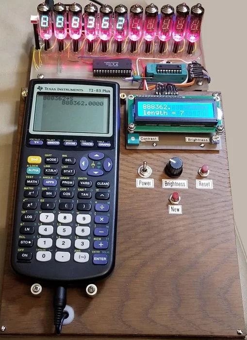
This project recreates a vintage calculator display using a TI-83+ interface to drive an LCD and 11 vacuum fluorescent display (VFD) tubes. A PIC 16F88 microcontroller retrieves calculation results from the calculator, while a PIC 12F683 acts as a boost converter for VFD power. The system utilizes an A6812SA driver to multiplex the displays, allowing users to view large numeric values with negative indicators and adjustable brightness.
Parts used in the VFD Display for the TI83+ Calculator:
- TI83+ Calculator
- LCD (2 x 16)
- PIC 16F88 Microcontroller
- A6812SA VFD Driver/Shift Register
- PIC 12F683 Microcontroller
- 11 IV-6 Type Rectangular LED VFD Tubes
- LEDs for tube illumination
- 100 ohm pots for current limiting
- ZIF socket
- Plastic tubes for alignment and support
This project builds upon the PIC/TI83+ interface developed by Thomas
Henry (see Nuts & Volts August 2013 – A Mathematics Engine for Microcontrollers). Acknowledgment, appreciation, and kudos to him for writing the TI-library for Great Cow Basic that made this project possible.
When I recently re-discovered that article, I imagined re-creating the only calculator that was available on campus when I was a Freshman in college. That calculator was in the basement of the Chemistry building, and students had to wait in line to get their 10 minutes on the beast, which displayed results on several large nixie tubes. My version uses VFDs, is much smaller, but still is reminiscent of that unit. In short, this project will display calculator values or results on both an LCD and 11 VFD tubes.
Step 1: Main Components
The main components are:
The TI83+ and LCD (2 x 16)
PIC 16F88 – interfaces with the calculator, sends serial data to the VFD driver (A6812SA)
A6812SA – VFD driver/shift register
PIC 12F683 – configured as a boost converter to provide the voltage to VFD grids and segments
11 VFD tubes – IV-6 type Rectangular LED – to indicate negative result
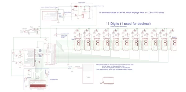
Step 2: Block Diagram
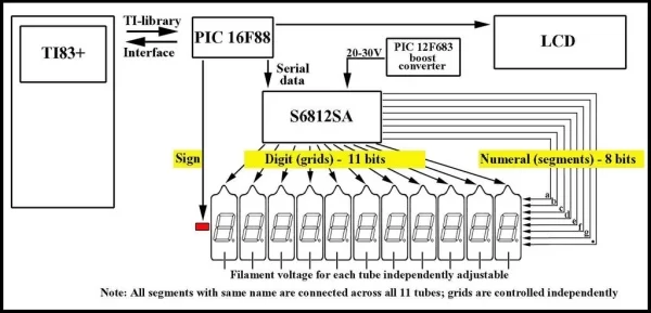
Since the TI83+ can only
display 10 characters at once, I elected to use 11 tubes, the extra for a decimal point. To drive the VFDs, I chose the A6812SA driver/shift register because I had it, now obsolete but still available, but you could use the MAX6921 which has the same pinout. These chips have 20 outputs; 19 are needed for this project.
Step 3: How It Works
How it works: (key code variables in bold):
A number or answer to a calculation on the TI83+ is stored into variable S. When the New button on the console is pushed, the number is retrieved from the calculator by the 16F88, and converted to a string named value (Thomas Henry’s TI-Library does all the heavy lifting here!). If the string is too long, i.e. has more characters than there are VFD tubes (11), the code prompts the user to try again with 10 or less characters. (10, not 11, because the code which converts the string may add a decimal or zero to the string). If the number is negative, an LED is turned on which indicates such, otherwise it is off. The string value is printed on the LCD. The characters are converted to binary numbers which code for which segments will be turned on in each VFD tube. Each of those binary numbers (variable called numeral) is paired, in the order of the original characters, with another binary number (variable digit) representing a numbered VFD tube. The 11 bits for each digit, and the 8 bits for each numeral and then fed serially into the shift register/VFD driver, occupying 19 bits of the 20 bit register. Then the 19 bits are latched, and appear on the output of the shift register, where they turn on one tube and its’ corresponding numeral segments. Tube 1 is turned on first, then tube 2, etc, in rapid succession such that persistence of vision makes it appear that all are on simultaneously (multiplexing). During the repeated running of the multiplexing loop, the user can perform additional calculations or entries on the calculator and store to S. At any time while the VFD display is on, another press of the button will retrieve the new value stored in S. Power for the VFD segments and grids (variable, for brightness control, up to ~34 V.D.C.) is obtained from the 12F683 configured as a boost converter, and power (~1.2 V.D.C.) for the VFD filaments is taken from the +5V.D.C. line, with current limited by precision 100 ohm pots. I had considered using AC drive for the filaments, as this helps avoid uneven illumination of segments, however the current demand for 11 filaments would have required multiple drivers and support components with increased circuit complexity. As uneven illumination is not a significant factor with single tubes, I opted for direct DC drive of the filaments, which also allows for individual voltage control of each filament.
The LCD provides simplified instructions for numeric entry, and as noted, provides feedback if too many digits are entered. In addition to also displaying the value, it displays the number of characters in that string. Tube brightness can be controlled on the console, and a reset button for the PIC 16F88 is provided. For effect, each tube is illuminated beneath by an LED.
Step 4: The Code
The code: As noted the code is written in Great Cow Basic (I used version 98.06).
PWM_for_VFD2.hex is the code for the PIC 12F683
TI83+VFD.hex is the code for the PIC 16F88
The 3 files ending in .txt are the original code for use with Great Cow Basic;
just remove the .txt ending to use.
Attachments
- PWM_for_VFD2.hexDownload
- TI83+VFD.hexDownload
- PWM_for_VFD2.gcb.txtDownload
- TI83+VFD.gcb.txtDownload
- TI-Library.gcb.txtDownload
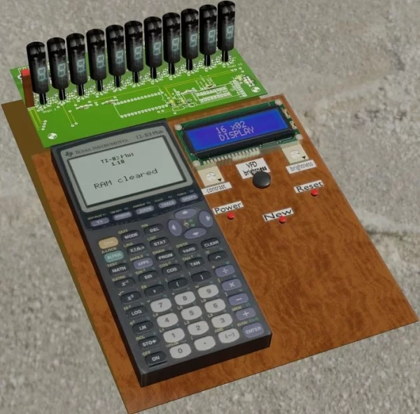
Step 5: Planning Mock-up in Blender
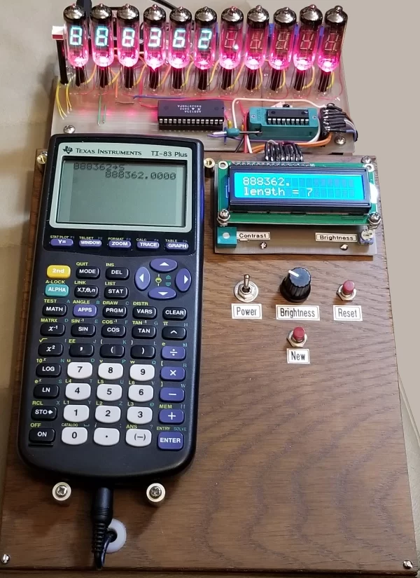
Step 6: Completed Project
Step 7: Construction Notes & IV-6 Pinout
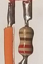
A ZIF socket was used in case I wanted to modify the code.
For easier alignment of the tubes during placement, I cut equal length plastic tubes as supports, which also doubled as holders for the LEDs and limiting resistors.
Step 8: Pre-operation Calibration
A couple of steps before you use the unit for the first time are important to prevent burning out some components! The boost converter has no feedback, so to avoid a large voltage and current spike, turn the brightness control all the way down before powering the unit on. Likewise, set the 100 ohm pots at maximum resistance so that the filaments receive little to no current. Now power on the unit and probe each filament pin with a VOM and set the voltage for each to ~1.2V; if this causes the filament to glow, turn the voltage down until the glow disappears; this will lengthen filament life.
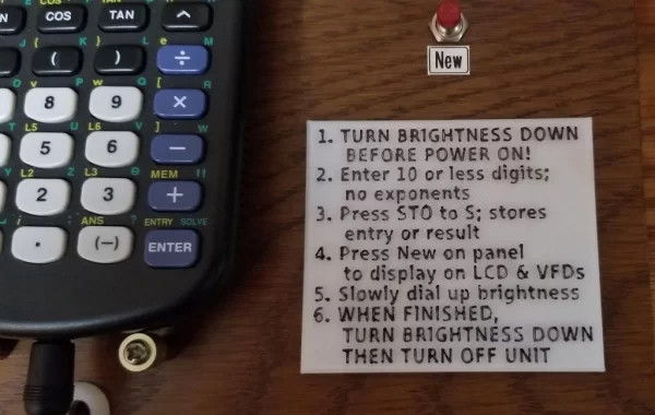
Step 9: Instructions for Operation
1. TURN BRIGHTNESS DOWN BEFORE POWER ON!
2. Enter 10 or less digits; no exponents
3. Press STO to S; stores entry or result
4. Press New on panel to display on LCD & VFDs
5. Slowly dial up brightness
6. WHEN FINISHED, TURN BRIGHTNESS DOWN, THEN TURN OFF UNIT
Step 10: The Schematic
Download the .pdf for higher
resolution schematic.
Attachments
Step 11: The Bill of Materials
Attachments
Step 12: 3D Printed Instructions
3D printed instructions to mount on the console.
Attachments
Source: VFD Display for the TI83+ Calculator
- How many characters can the TI83+ display at once?
The TI83+ can only display 10 characters at once. - What is the purpose of the extra VFD tube?
The 11th tube is used for a decimal point since the calculator displays 10 characters. - Can I use a MAX6921 instead of the A6812SA?
Yes, you could use the MAX6921 because it has the same pinout as the A6812SA. - How is the voltage for VFD filaments controlled?
Power for the filaments is taken from the +5V.D.C. line with current limited by precision 100 ohm pots. - Why was DC drive chosen over AC drive for the filaments?
DC drive was chosen because AC would require multiple drivers and increased circuit complexity for 11 filaments. - What happens if a number has more than 10 digits?
The code prompts the user to try again with 10 or less characters because the conversion process may add a decimal or zero. - How is the brightness of the tubes adjusted?
Tube brightness is controlled via a variable up to ~34 V.D.C. obtained from the boost converter. - What should be done before powering on the unit?
You must turn the brightness control all the way down and set the 100 ohm pots to maximum resistance. - Which programming language was used for the code?
The code is written in Great Cow Basic. - How are the VFD tubes illuminated simultaneously?
The tubes are turned on in rapid succession using multiplexing so persistence of vision makes them appear on simultaneously.