Summary of How to interface keypad with PIC12F675
This article shows a simple method to interface a 3x4 or 4x4 keypad to a PIC12F675 by encoding each key as a unique voltage and reading it via the PIC12F675 ADC (GP4/AN3). Using diodes on rows and different column pull-downs (ground, Schottky, 2.7V and 3.0V zener) produces distinct voltages so only one ADC pin is required; LCD output via a 4094 shows the pressed key. Code is provided in C (MPLAB + HI-TECH C) and Proteus simulation is available for download.
Parts used in the Keypad with PIC12F675 Project:
- PIC12F675 microcontroller
- 4x4 or 4x3 keypad
- 1N4007 diodes (or any ~0.7V diodes) for rows
- Schottky diode for column 2
- 2.7V zener diode for column 3
- 3.0V zener diode for column 4
- 470 ohm pull-up resistor
- LCD module (interfaced via 4094 shift register)
- 4094 IC (for LCD interface)
- Ground connection for column 1
- Power supply (for PIC and components)
This post provides a simple method to interface any keypad (e-g 4×4 or 4×3 etc) with PIC12F675 microcontroller. The code for PIC12F675 is written in C language using MPLAB with HI-TECH C compiler. You can download this code from the ‘Downloads‘ section at the bottom of this page.
In this post, it is assumed that you know,
- How to use ADC of PIC12F675 microcontroller. If you don’t then please read this page.
- How to interface LCD with PIC12F675 microcontroller. If you don’t then please read this page.
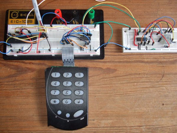
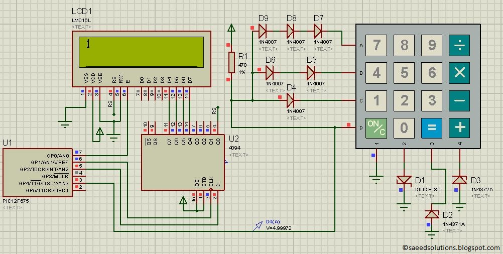
The circuit required to interface keypad with PIC12F675 is shown below.
The result of simulating the code in Proteus is shown above in the figure. This code is written in such a way that when you press any key from the keypad, then the value of that key is displayed on the LCD. For example, in the above figure LCD screen is displaying ‘1’, because this picture was taken after pressing ‘1’ from the keypad.
In the above circuit, PIC12F675 is running on it’s internal 4MHz oscillator. GP0, GP1 and GP2 pins are used to interface LCD through 4094 IC as explained in the “PIC12F675 LCD Interfacing Code + Proteus Simulation” post. LCD is used here just to show the pressed key value. Usually 8 pins are used to interface 4×4 keypad with any microcontroller. 4 pins are used to attach columns and 4 pins are used to attach rows and scanning algorithm code is used to check for any pressed key.
But PIC12F675 doesn’t have 8 pins. By using some diodes we can generate different voltage on each pressed key on a single wire (as shown above in the circuit). And then by using built-in ADC of PIC12F675 we can read this voltage value to determine pressed key easily. In this way by using only one pin of PIC12F675 we can successfully interface keypad with it. To interface keypad, only GP4(AN3) pin is being used in the circuit shown above.
In the above circuit, rows of the keypad have 1N4007 diode attached with them. If you don’t have 1N4007 diode, then any simple 0.7 volt[1] diode can be used here. RowA has 3 diodes, RowB has 2 diodes, RowC has one diode and RowD has no diode attached with it. These diodes are pulled-up from one side by a 470 ohm resistor. Column1 wire of keypad is attached with the ground. Column2 is attached with a schottky diode[2]. Column3 is attached with a 2.7v zener diode. Column4 is attached with a 3.0v zener diode. Using this circuit you can easily interface keypad with PIC12F675 microcontroller.
Code
The code of the main function is shown below.
Downloads
Keypad interfacing code using PIC12F675 was compiled in MPLAB v8.85 with HI-TECH C v9.83 compiler and simulation was made in Proteus v7.10. To download code and Proteus simulation click here.
For more detail: How to interface keypad with PIC12F675
- How does this method read multiple keys with limited pins?
Different diodes and pull components create unique voltages for each key so the PIC12F675 ADC on one pin can distinguish keys. - Which PIC12F675 pin is used for the keypad ADC input?
GP4 which is AN3 is used as the ADC input for the keypad. - What diodes are used on keypad rows?
1N4007 diodes are used on rows, or any simple ~0.7V diode if 1N4007 is unavailable. - How are the keypad columns configured?
Column1 to ground, Column2 via a Schottky diode, Column3 via a 2.7V zener, and Column4 via a 3.0V zener. - How is the pressed key value displayed?
The value is displayed on an LCD interfaced through a 4094 shift register using GP0, GP1 and GP2. - What oscillator does the PIC12F675 use in the circuit?
The PIC12F675 uses its internal 4MHz oscillator in the shown circuit. - Which compiler and tools were used for the code and simulation?
Code was compiled with HI-TECH C in MPLAB v8.85 and simulated in Proteus v7.10. - Can other diodes replace the 1N4007?
Yes, any simple 0.7 volt diode can be used instead of 1N4007.