Summary of Efficient Sun-Following Robot: A Solar Tracker with Microcontroller Control
The article describes designing an autonomous Solar Tracker Robot (STR) that maximizes solar panel exposure using LDR sensors, a digital compass, and servo/DC motors controlled by a PIC16F877A microcontroller; programming is done in MPLAB IDE v8.30 and performance data logged with a Fluke 1750 power quality recorder.
Parts used in the Solar Tracker Robot (STR):
- PIC16F877A microcontroller
- Light Dependent Resistors (LDR) - two sensors
- Digital Compass Module HMC6352
- Servo motors (three total)
- Modified DC servo motors (two for base realignment)
- Servo motor driver (L293D)
- Limit switches
- Power supply (for microcontroller and motors)
- MPLAB IDE v8.30 (programming environment)
- Fluke 1750 power quality recorder (for data collection)
Abstract
The impending global challenge of dwindling non-renewable fuel resources underscores the urgency of transitioning towards renewable energy alternatives like solar power. However, the efficacy of solar energy generation hinges on the intensity of solar irradiation. This project aims to address this by designing and implementing an automatic Solar Tracker Robot (STR) capable of optimizing light capture.
The primary objective is to enhance the efficiency of solar energy conversion by ensuring maximum exposure to sunlight on the solar panel. The key components of the robot include a PIC16F877A microcontroller, various sensors, servo motors, and a digital compass. Utilizing two Light Dependent Resistors (LDR), the robot is programmed to detect sunlight, with the servo motor adjusting the orientation of the solar panel to maximize light reception.
Furthermore, a digital compass aids in determining the robot’s position. In instances where the robot deviates from its intended position, two modified DC servo motors realign it. Programming for the robot is executed using MPLAB IDE v8.30. To analyze the power conversion efficiency of the solar panel, data is collected using a Fluke 1750 power quality recorder.
1. INTRODUCTION
With the finite availability of non-renewable fuels, contemporary scientists are actively seeking alternative energy sources. Fossil fuels, aside from their limited supply, pose numerous environmental challenges, as their combustion byproducts contribute to pollution, leading to phenomena like acid rain and global warming. Transitioning to clean energy sources such as solar power offers a promising solution to enhance the quality of life on Earth.
Solar energy, abundant and non-polluting, is currently underutilized compared to other renewable sources like hydro and wind power. This disparity can be attributed to the relatively low conversion efficiency of solar cells and their associated high costs. To maximize the utility of solar energy, two approaches are commonly employed: optimizing absorber materials to enhance conversion efficiency and implementing tracking systems to augment incident radiation rates.
Traditionally, solar cells are fixed either on rooftops or on the ground, limiting their exposure to maximum sunlight as the sun’s position changes throughout the day. Existing research predominantly focuses on enhancing the efficiency of solar cells. This paper introduces the Solar Tracker Robot (STR), designed to optimize solar power efficiency by aligning solar cells with the sun’s movement to track optimal sunlight angles.
The STR employs a tracking system integrated into the solar cells’ assembly, ensuring they remain parallel to the sun’s rays. This orientation adjustment can significantly increase conversion efficiency, potentially from 20% to 50%. Notably, the STR is designed for portability and does not require installation, making it suitable for placement in open spaces exposed to direct sunlight. Equipped with a digital compass, the STR autonomously adjusts its position, enabling the solar panel to rotate along one axis from east to west while ensuring the robot’s front always faces north.
2. LITERATURE REVIEW
In the past, numerous projects focusing on solar tracking systems have contributed to advancements in this field. The following are examples of such previous projects.
A. Microprocessor Based Solar Tracking System Using Stepper Motor
Utilizing a microprocessor to oversee the tracking system involves interfacing it with various components. The benefit of employing a microprocessor lies in its capacity to accommodate additional functions through the incorporation of supplementary components [6]. Nonetheless, the implementation necessitates external components for program memory, RAM, ROM memory, input and output ports, and ADC. This leads to elevated project costs and heightened project intricacy.
B. Miniature Solar Tracker
The solar tracker employed in this project relies on a microcontroller and operates on a single-axis tracking system driven by a DC motor. Such single-axis systems rotate along their axis to follow the sun, orienting eastward in the morning and westward in the evening. This project offers affordability and simplicity in control, as the solar tracking system is mounted on a tripod [7]. However, lacking intelligent feedback to adjust the position of the solar tracker if it deviates, it cannot optimize sunlight tracking to its fullest potential.
C. Different Tracking Strategies for Optimizing the Energetic Efficiency of A Photovoltaic System
This project involved the implementation of a dual-axis tracing system coupled with a fuzzy logic neural controller. The dual-axis tracking systems demonstrate exceptional precision in tracing the sun’s path throughout the year [8]. Consequently, they offer superior efficiency compared to single-axis tracking systems, albeit at a higher cost. This is attributable to the increased utilization of electrical and mechanical components. Additionally, the complexity and challenge of the control component are heightened in this setup.
D. Solar Tracker Robot Using Microcontroller
The Solar Tracker Robot (STR) operates on microcontroller technology and is designed to orient the solar panel along a single axis, spanning from east to west and back. A servo motor is employed as the actuator for repositioning the solar panel, chosen for its compact size and high torque capabilities. The STR autonomously aligns itself to consistently face a specific direction, ensuring the solar panel captures optimal sunlight. This self-adjustment feature remains active even when external forces attempt to displace the STR.
3. METHODOLOGY
In this project, the robotic tracking system operates with two Light Dependent Resistors (LDRs) serving as input signals, while a servo motor acts as an actuator to adjust the position of the solar panel. Additionally, the robot’s navigation primarily relies on digital compass data for error correction. This data is transmitted to the microcontroller through Inter Integrated Circuit (I2C) interfacing. The controller, powered by a PIC16F877A chip, orchestrates the entire circuit, managing the LDRs, servo motors, and digital compass components.
A. System Architecture
The diagram depicted in Figure 1 illustrates the comprehensive structure of the entire system, encompassing light sensors, a digital compass, limit switches, three servo motors, and a servo motor driver. The system comprises two primary components as delineated in the figure: the tracker and the base. Serving as the central processing unit, the PIC16F877A chip embedded within the control circuit governs the entire system’s operations. In this architecture, I2C communication protocol is employed to establish connectivity with slave devices, notably the Digital Compass Module HMC6352.
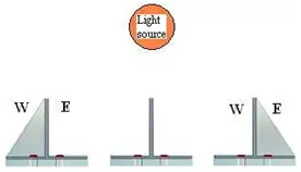
B. Sensor Arrays
The LDR sensors will be configured as depicted in Fig. 2. Under uniform illumination, both sensors exhibit similar resistances. However, if one sensor is shaded, its resistance surpasses the expected range. In response, the PIC microcontroller initiates motor activation to adjust both sensors for uniform lighting [9]. If the western cell (W) is shaded, the tracker pivots eastward; conversely, if the eastern cell (E) is shaded, the tracker shifts westward. The flowchart illustrating the movement of the solar panel is presented in Fig. 3.
C. Digital Compass
The digital compass serves to determine the robot’s current orientation. The Solar Tracker Robot (STR) is initially aligned to face north, designated as 0°, enabling the solar panel to effectively track the sunlight from east to west. If the STR deviates from this set position, it will engage in the operation depicted in Figure 4.
D. Main Board Control Unit
The diagram depicted in Fig. 5 illustrates the schematic layout of the STR (Solar Tracker Robot) system. This system comprises a microcontroller, two Light Dependent Resistor (LDR) sensors, a digital compass, a motor driver (L293D), servo motors, limit switches, and various other components.
- What is the primary objective of the Solar Tracker Robot (STR)?
The primary objective is to enhance solar energy conversion efficiency by ensuring maximum exposure of the solar panel to sunlight. - How does the STR detect sunlight direction?
The STR uses two Light Dependent Resistors (LDRs) as sensors to detect differential illumination and guide the servo motor to align the panel. - What role does the digital compass play in the STR?
The digital compass determines the robot's orientation so the STR can maintain its front facing north and correct positional deviations. - Which microcontroller is used to control the STR?
The STR is controlled by a PIC16F877A microcontroller. - How are motors driven in the STR system?
Servo motors are used to adjust the solar panel and two modified DC servo motors realign the robot; a motor driver L293D is included in the control circuitry. - Can the STR correct its position if displaced?
Yes, the STR uses the digital compass and two modified DC servo motors to realign itself when it deviates from the intended position. - What communication protocol is used for the digital compass interface?
The I2C communication protocol is used to interface the digital compass module HMC6352 with the microcontroller. - What software is used to program the STR?
Programming for the STR is performed using MPLAB IDE v8.30. - How is the power conversion efficiency of the solar panel analyzed?
Data for analyzing the panel's power conversion efficiency is collected using a Fluke 1750 power quality recorder.