Summary of 3 LED Bike Light for PIC10F200
This project is a low-power, multi-function LED bike light using a PIC10F200 microcontroller to drive three individually controlled LEDs. It runs from 2–5 V, draws <1 µA in standby, and uses one push button for long-press standby entry/exit and short presses to cycle seven user modes. Two PCB variants are shown (8-pin PDIP and SOT-23). Resistor values should be chosen for LED type and supply voltage; a 100nF decoupling capacitor is included. Firmware stores LED patterns in a lookup table and can be modified with a PIC programmer.
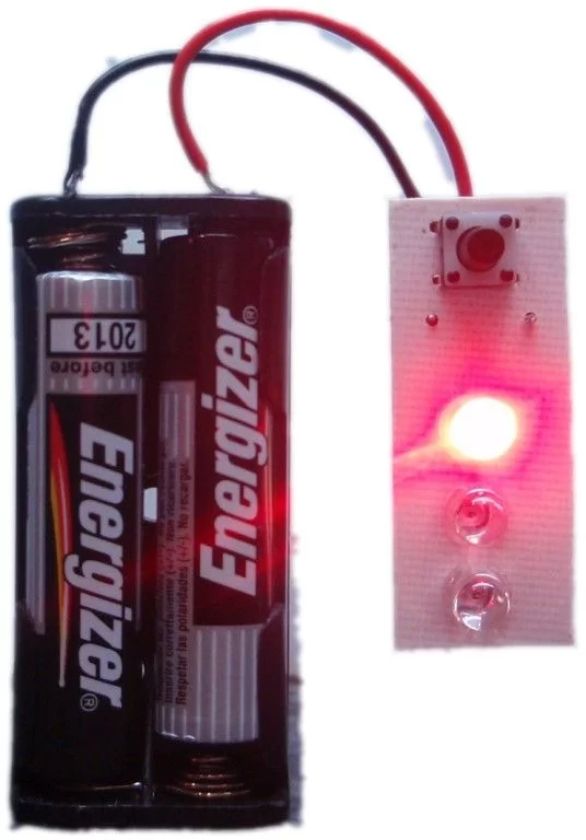
Parts used in the 3 LED Bike Light for PIC10F200:
- PIC10F200 (8-pin PDIP or SOT-23 package)
- Three high-brightness LEDs (red or white)
- Current-limiting resistors (example values: 100R, 68R, 10R depending on supply and LED)
- Push button switch (single)
- 100 nF decoupling capacitor
- Battery supply (2 to 5 V source, e.g., 2 x AAA for 3 V)
- PCB or protoboard and wiring
Description
This project is a multi-function LED bike (cycle) light using 3 LEDs.
It is based on a PIC10F200 baseline microcontroller, running from a supply voltage of 2 to 5 volts. In standby mode it consumes a current of less than 1µA making it perfect for battery powered operation.
It uses three individually driven high brightness LEDs, and a single push button switch for turning the light on/off and changing operating modes when on.
The features written into the program for this project address what I consider to be three shortcomings of LED bike lights on the market today.
- they can easily be turned on accidentally
- they require you to cycle through all the modes to turn them off
- you may have to cycle though several modes to get the one you want after switching it on
To deal with point 1 this light requires the mode button to be held for >2 seconds to enter / exit standby mode. This helps prevent it from being accidentally turned on when removed from the bike and stowed in a pocket or bag.
When the light is powered-on, a short press of the mode button cycles through all available modes. The default firmware supplied features seven modes and as long as the power to the circuit isn’t removed, it will come out of standby and run the last selected mode.
Disclaimer:
The legality of this bike light for on-road use depends on the laws and regulations in the country of use. It should be assumed it is not legal to use it on the road unless you have establish yourself that the use of such a device is permitted.
Schematic
Two schematics are shown, one for the PIC10F20x 8-pin PDIP package, the other for the 6-pin SOT-23 package. The two parts have different pin outs.
Resistor values are shown as 100R and these are conservative values for use from a 3 to 4.5 volt battery supply and high brightness red LEDs. The actual value used should be selected based on the supply voltage, the type of LEDs used and if powered from a battery the desired battery life.
Running from a 3 volt supply (2 x AAA batteries) you could use 68R resistor with red LEDs and 10R with white LEDs.
![]() Resistor value notation.
Resistor value notation.
100R means 100 ohms, 4K7 would be 4,700 ohms
Circuit / Firmware Description
There are two functionally identical versions of the project presented on this page; a small easy to assemble version using the 8-pin PDIP version of the PIC10F20x and a very small version based on the SOT23 package PIC and surface mount components.
The circuit drives 3 LEDs from the I/O pins of the PIC microcontroller. A single push button switch provides standby/power-on function as well as mode selection.
The circuit can operate from a voltage in the range 2 to 5 volts although you will need to take into account the forward voltage drop of the LEDs used; red LEDs typically need at least 2 volts, white LEDs 3 volts. Current consumption in operation depends on the LEDs used and the choice of current limiting resistors. Typically it will be in the range of 10 to 30mA. In standby current consumption drops to less than 1µA making it well suited to battery operation. The 100nF capacitor is used for decoupling of the power supply to the PIC.
The LED functions are defined by a lookup table in the PIC’s program firmware. If you have access to a PIC programmer and want to edit or modify these you can download the source code (see bottom of this page).
For more detail: 3 LED Bike Light for PIC10F200
- What microcontroller does the project use?
The project uses a PIC10F200 microcontroller available in 8-pin PDIP or SOT-23 packages. - How many LEDs does the circuit drive?
The circuit drives three individually controlled high-brightness LEDs. - What supply voltage range does the light support?
The circuit operates from 2 to 5 volts, taking LED forward voltage into account. - How is accidental turn-on prevented?
The mode button must be held for more than 2 seconds to enter or exit standby, preventing accidental activation. - How are operating modes changed?
A short press of the mode button cycles through the available modes when powered on. - What is the standby current consumption?
Standby current consumption is less than 1 microampere. - Can the LED mode patterns be modified?
Yes, the LED functions are defined by a lookup table in the firmware and can be changed with a PIC programmer using the source code. - What decoupling is recommended for the power supply?
A 100 nF decoupling capacitor is used for power supply decoupling to the PIC.