
Summary of Serial LCD Module using PIC16F88
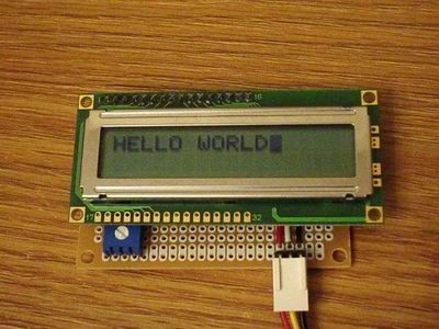
Summary: A DIY serial LCD module converts a parallel 16x2 character LCD to work with a single MCU serial input pin. The project uses a PIC16F88 (internal oscillator and USART) to drive the LCD in 4-bit mode, mapping RA0–RA3 to D4–D7, RB0 to RS, and RB1 to E. Serial commands prefixed with 0xFE control display functions. Communication is 8N1 at 9600 baud.
Parts used in the Serial LCD Module:
- PIC16F88 microcontroller
- 16x2 character LCD (HD44780 compatible)
- Connections/wiring between MCU and LCD (RA0-RA3, RB0, RB1)
- Ground connection for R/W of LCD
- Power supply for MCU and LCD (Vcc, GND)
Many times when I’m working with a small MCU such as 8 pins or 18 pins MCU. I found that I don’t have enough MCU pins for parallel LCD display. So it’s good to have a one-pin-require LCD module for experiment. Acctually, serial LCDs are sale on the market but still I built it myself becasue I can do it and it’s cheap.
It’s a very simple schematic, I use PIC16F88 becasue It has internal oscillator and Usart module. And a 16 x 2 LCD character and numeric. PORTA is a data port connect to D4 – D7, PORTB 0 and 1 are control port connect to RS and E. RB2 is input pin for serial input data. For serial LCD, 0xFE is consider as a prefix command. The command codes are list below:
1: Clear screen.
2: Home.
12:Hide cursor.
13: Show blink cursor.
14: Show underline cursor.
16: Move cursor one character left.
20: Move cursor one character right.
24: Scroll display one character left.
28: Scroll display one character right.
192: Move to fisrt character of second line.
The communication format is 8-bit data, one stop bit and no parity (RS-232). The default BAUD rate is fix at 9600.
The code.
/*
* Project name:
Serial LCD moduel from parallel LCD
* Copyright:
Nicholas Sirirak
* Description:
* Test configuration:
MCU: PIC16F88
Dev.Board: –
Oscillator: HS, 8.0000 MHz internal
Ext. Modules: –
SW: mikroC v8.1.0.0
* NOTES:
HW connection
MCU LCD
RA3 <——–> D7
RA2 <——–> D6
RA1 <——–> D5
RA0 <——–> D4
RB0 <——–> RS
RB1 <——–> E
R/W —> GND
*/
void main(){
For more detail: Serial LCD Module using PIC16F88
- What MCU is used in the project?
The project uses a PIC16F88 microcontroller. - How is the LCD connected to the MCU?
RA3 to D7, RA2 to D6, RA1 to D5, RA0 to D4, RB0 to RS, RB1 to E, and R/W tied to GND. - How many MCU pins are required for the serial LCD module?
The design uses one serial input pin (RB2) plus four data/control pins (RA0–RA3 and RB0–RB1 are used to drive the LCD internally), so the MCU receives data on RB2. - What is the serial communication format and baud rate?
Communication is 8-bit data, one stop bit, no parity (8N1) with a default baud rate of 9600. - What prefix indicates a command for the serial LCD?
0xFE is used as the prefix command byte. - What command clears the screen?
Command code 1 clears the screen. - Which command moves the cursor to the first character of the second line?
Command code 192 moves to the first character of the second line. - How do you show a blinking cursor?
Send command code 13 to show a blink cursor. - How is the LCD operated electrically for read/write?
R/W is tied to GND so the LCD is write-only from the MCU.
