


Summary of PC Based Digital Voltmeter Using PIC 16F877A
This project is a PC-interfaced 0–5 V digital voltmeter using the PIC16F877A 10-bit ADC, providing ~4.8828 mV resolution. It reads analog on AN0, configures ADCON0/ADCON1 for channel, result format, and reference selection, starts conversions via ADCON0, and sends measured voltages over UART to a computer. A MAX232 serial level-shifter is required for RS-232 interfacing (not shown in the circuit). The design typically uses high-level language ADC routines (e.g., adc_read) to obtain conversion results.Parts used in the PC Based Digital Voltmeter Using PIC 16F877A:
- PIC16F877A microcontroller
- Analog input source (0–5 V)
- MAX232 level shifter (for RS-232 interface to PC)
- Serial cable (RS-232) to computer
- Power supply (suitable for PIC16F877A)
- Decoupling capacitors
- Clock oscillator/crystal for PIC
- PCB or breadboard and wiring
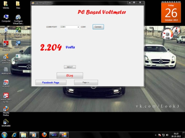
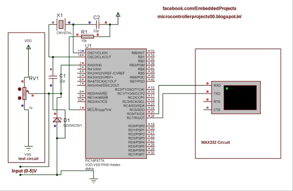
This is a simple voltmeter which measures 0-5V at a precision of 4.8 mV. This is a simple design using inbuilt ADC of PIC 16F877A. PIC 16F877A have 8 channel 10bit ADC. This is a computer interfaced project. Measured voltage is output in serial interface software in computer. There is a serial interface circuit (MAX232) is necessary for interfacing with computer, which is not included in the circuit. Please check PIC Serial Communication Tutorial (UART) for the circuit and more details.
 Using one of the most popular 8 bit PIC 16f877A, for instance, reading the datasheet, we'll find that the ADC modules (10 bit) are controlled by four different registers. The first two, ADCON0 and ADCON1, are used to set and start the ADC module. When high level language is used, the programmer doesn't need to care a lot of the register connected to the results because they are normally stored in a variable by a routine of the language itself (adc_read, for instance, using mikroc).
The ADCON0
As we can see this registers are 8 bit registers where.
- bit6 and bit 7 are used to set the frequency of the conversions.
- bits 3, 4 and 5 are used to select the pins of the microcontroller enabled to the adc conversions.
- bit 2 represents the status of the conversion procedure.
- bit 0 starts the conversion.
 Regarding the second register, ADCON1, it must be set for two reasons: to select the format of the result value (bit 7), to select (bit0...bit3) the reference voltage and to set the port configuration control bits according to the following table
This circuit uses AN0 channel of ADC. The voltage conversion is employed in a logic, 16F877A have 10 bit ADC. That is, it can have 1024 levels. Reference voltage is fixed at
0 – 5 V Analog I/P is mapped to one of the 1024 levels (0-1023 Digital Count)
Resolution = 5/(1024) (as it is 10 bit ADC)
= 5/1024
= 4.8828 mV It means that for a change in 4.8828mV, the binary output changes by 1.
For more detail: PC Based Digital Voltmeter Using PIC 16F877A
- What voltage range does this voltmeter measure?
It measures 0–5 V analog inputs as stated in the article. - What resolution does the voltmeter provide?
The resolution is 5/1024 = 4.8828 mV per ADC step. - Which ADC channel is used in the circuit?
The circuit uses the AN0 channel of the PIC16F877A ADC. - Which PIC microcontroller is used?
The project uses the PIC16F877A microcontroller. - Do I need a MAX232 for computer interfacing?
Yes, a MAX232 serial interface circuit is necessary for interfacing with a computer and is not included in the provided circuit. - How many bits is the ADC in the PIC16F877A?
The ADC is 10 bit, providing 1024 discrete levels (0–1023 counts). - Which registers control the ADC in PIC16F877A?
The ADC is controlled by ADCON0 and ADCON1 registers as described in the article. - What does ADCON0 bit 0 do?
ADCON0 bit 0 starts the conversion according to the article. - What does ADCON1 configure?
ADCON1 sets result format, reference voltage selection, and port configuration control bits. - Is the ADC result handled automatically in high level languages?
Yes, high level language routines like adc_read typically store results in a variable so the programmer does not manage result registers directly.
Related projects
PIC16F877 Driving LCD in 4-Bit Mode using PIC16F877 with Proteus Simulation
Introduction This microcontroller project shows how a PIC16F877 can drive an LCD display using 4-bit mode inside a Proteus simulation.The project demonstrates...
Programmers & ICSP · PIC16F877AEPE PIC/LCD Demo using PIC16F877 with Proteus Simulation
IntroductionThe EPE PIC/LCD Demo is a classic microcontroller project that demonstrates how a PIC16F877 can fully control a PG12864F graphical LCD.Designed as...
Motors & Robotics · PIC16F877AEfficient Sun-Following Robot: A Solar Tracker with Microcontroller Control
Abstract The impending global challenge of dwindling non-renewable fuel resources underscores the urgency of transitioning towards renewable energy alternatives like solar power....
Meters & Test Instruments · PIC16F688Determine capacitance by measuring the charging time using PIC16F688
When TEST botton is pressed, RA3 pin is set to "1". R2 and R3 are divide the voltage to 1/2 Vra3 which...
Meters & Test InstrumentsFrequency Meter Using Microcontroller
This tutorial simply states how to calculate frequency of a pulse source using a microcontroller. Story https://youtu.be/NAoj-HLRIro This tutorial simply states how...
Meters & Test Instruments · PIC16F84ADigital thermometer with PIC16F84 circuit
This electronic project is a very simple thermometer that is based on the PIC16F84A microcontroller, designed by Microchip. Why to use a...

Ibrar Ayyub
I am an experienced technical writer holding a Master's degree in computer science from BZU Multan, Pakistan University. With a background spanning various industries, particularly in home automation and engineering, I have honed my skills in crafting clear and concise content. Proficient in leveraging infographics and diagrams, I strive to simplify complex concepts for readers. My strength lies in thorough...