Summary of PIC 16f877 microcontroller based RPM Meter
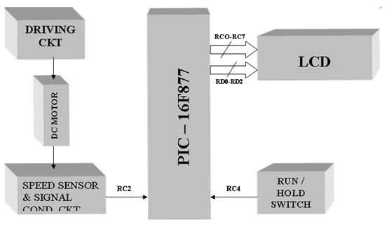
The project builds an RPM meter using a PIC16F877 microcontroller to measure DC motor speed. A speed sensor’s conditioned pulses feed Timer1 (TMR1/RC2) as external clock; counts over one second are multiplied by 60 to get RPM. Operation has RUN (measure each second) and HOLD (display previous value) modes toggled by a pushbutton (RC4). Results and mode are shown on an LCD (data RC0–RC7, control RD0–RD2). Timer0 provides 1/16 s time slices via interrupts. Motor, driver, sensor, and signal-conditioning circuits are external.
Parts used in the RPM meter:
- PIC16F877 microcontroller
- Speed sensor (tachometer or pulse sensor)
- Signal-conditioning circuit for sensor pulses
- DC motor (external)
- DC motor driver circuit (external)
- 16x2 or similar LCD display
- Push button switch for Run/Hold (connected to RC4)
- Supporting passive components (resistors, capacitors)
- Power supply for microcontroller and motor
- Crystal or clock source for PIC (implied from code timing)
Summary: The speed of the motor is measured in Rotations per Minutes,RPM.The RPM Meter is to read the running speed of Motor like DC MOTOR. Here the speed of the DC Motor is sensed with the help of a speed sensor and it is signal conditioned to have pulses which given as Timer1 clock input of PIC Microcontroller, configured to accept external clock input.The count value in Timer1 for one second represents speed in seconds which can be converted into RPM by multiplying the count by 60.The Display of the speed will be on Lyquid Crystal Display LCD .
AIM :
To develop a RPM meter using microcontroller & to display the speed on LCD Display PIC Microcontroller 16F877.
INTERFACING:
- Pulses from speed sensor connected to TMR1 clock input-RC2
- Run/Hold push button switch connected to –RC4
LCD Display –
- Data lines connected to Port C – RC0: RC7
- Control lines connected to Port D – RD0: RD2
- Timer0 used for generating time slice of 1/16 sec in interrupt driven mode
NOTE: DC motor, DC motor driver circuit, speed sensor, signal-condition circuit to be Provided.
DESCRIPTION:
Pulses from the speed sensor, after signal conditioning, is connected to Timer 1 input.
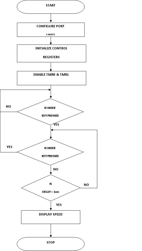
RPM meter works in two modes viz RUN & HOLD. The mode toggles for every push of the mode selection push of the mode selection push button switch:
HOLD Mode: Previous value of the speed is displayed
RUN Mode: Speed is measured for every second
- By default meter will be in HOLD mode with display ‘00’.
- Mode of operation and the speed are displayed on LCD
Figure4: Functional Flow Chart for RPM Meter
LIST P=16F877
#INCLUDE”P16F877.INC”
CBLOCK 20H
HEX1
HEX2
DEC1
DEC2
DEC3
DEC4
DEC5
DD1
DD2
DV1
DV2
Q2
Q1
TEMP
DISNO
DLOC1
DLOC2
ENDC
ORG 00H
GOTO MAIN
 MAIN CLRF CCP1CON ; CCP Module is off
CLRF TMR1H ; Clear Timer1 High byte
CLRF TMR1L ; Clear Timer1 Low byte
CLRF CCPR1L
CLRF CCPR1H
CLRF INTCON ; Disable interrupts and clear T0IF
BSF STATUS, RP0 ; Bank1
BSF TRISC, 2 ; Make CCP pin input
CLRF TRISD
CLRF TRISE
CLRF PIE1 ; Disable peripheral interrupts
BCF STATUS, RP0; Bank0
CLRF PIR1 ; Clear peripheral interrupts Flags
MOVLW 07 ; Capture mode, every 4th rising edge
MOVWF CCP1CON
BSF STATUS, RP0
BSF PIE1, CCP1IE
BCF STATUS, RP0
MOVLW 21H
MOVWF T1CON ; Timer1 starts to increment 1:8 PRESCALAR MODE
; The CCP1 interrupt is disabled,
; do polling on the CCP Interrupt flag bit
Capture_Event
BCF T1CON, TMR1ON; off the timer after capturing the 4th pulse
BANKSEL TRISA
CLRF TRISC
BANKSEL PORTA
BCF PIR1, CCP1IF ; This need to be done before next compare
MOVF CCPR1L, 0
MOVWF HEX1
MOVF CCPR1H, 0
MOVWF HEX2
BCF STATUS, C ; for performing right shift
RRF HEX2 ; dividing the period by 2 i,e right shift
RRF HEX1;
CALL DIVIDE ; converting the period into frequency i,e RPS=Fclk / (capture period)
For more detail: PIC 16f877 microcontroller based RPM Meter
- How is motor speed measured?
Speed sensor pulses, after signal conditioning, are fed to Timer1 as an external clock; the Timer1 count for one second is multiplied by 60 to obtain RPM. - Which microcontroller is used?
The PIC16F877 microcontroller is used. - How are RUN and HOLD modes selected?
A push button connected to RC4 toggles between RUN and HOLD modes on each press. - Where is the speed displayed?
The speed and mode are displayed on an LCD connected with data lines on RC0–RC7 and control lines on RD0–RD2. - Which pin receives sensor pulses?
Pulses from the speed sensor are connected to the Timer1 clock input at RC2 (TMR1). - What does HOLD mode do?
HOLD mode displays the previous measured speed value; by default the meter shows 00 in HOLD. - How is timing for measurement provided?
Timer0 is used to generate 1/16 second time slices in an interrupt-driven mode to manage timing. - Is signal conditioning required?
Yes, the speed sensor output must be signal conditioned before connecting to Timer1; a signal-conditioning circuit is provided externally. - What initial configuration is done in code?
The code clears and configures TMR1, CCP, interrupt flags, and sets CCP capture mode and T1CON for Timer1 with a 1:8 prescaler.