Summary of Designing Your Ideal Alarm Clock: An Introduction to PIC18
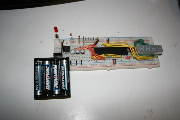
This lab guides creating an alarm clock on a PIC18 microcontroller using C, covering interrupts, DAC, and music playback. It includes hardware setup (buttons, LM60 temperature sensor, 20 MHz crystal, speaker, multi-digit seven-segment display with resistors and wiring), and step-by-step MPLAB C18 project creation and a first C program to toggle seven-segment outputs.
Parts used in the Alarm Clock Project:
- PIC18F4550 microcontroller
- Full color LED (optional)
- Pushbutton switches (placed at A28, A29, A30)
- LM60 temperature sensor
- 20 MHz crystal
- Speaker
- Two-digit / four-digit seven-segment display
- 470 ohm resistor (for decimal point)
- Assorted jumper wires
- Pickit2 programmer/debugger
Within this laboratory session, you’ll employ the C language to create an alarm clock, delving into the implementation of “C” programs on the PIC18 microcontroller. Additionally, you’ll gain insights into utilizing interrupts, executing digital-to-analog conversion, and incorporating music playback capabilities on the PIC18.
This project operates on a team basis, allowing a maximum of two members per team. While individual work is permissible, all projects will be assessed using identical grading criteria.
Step 1 .Intial Setup
Take out the Full Color LED and keep it in a secure place. You might opt to utilize it at a later stage in this project.
Shift the button cables two positions to the right, so they are now situated at A28, A29, and A30.

Next, locate the temperature sensor identified as the black semi-cylinder with three legs, labeled LM60. Take care not to mistake it for other transistors. Place the temperature sensor into the designated positions at E19, E20, and E21 as indicated, ensuring the flat face is directed towards you. Establish connections by linking A19 to +5V and A21 to 0V. Additionally, introduce a wire leading from the center of the sensor to A26, the designated analog input. It is crucial to correctly connect the temperature sensor to the power source to prevent damage or overheating.

Attach a 20MHz crystal to A37 and A38 for enhanced precision in the microcontroller’s clock. Previous endeavors relied on the internal clock of the CPU, which lacks the accuracy provided by the crystal.

Connect the speaker to terminal A41 and ground. The speaker will produce tones by utilizing the PWM output originating from RC2.

Next, proceed to link a resistor to the segment aligning with the decimal point. Establish a connection using a 470-ohm resistor (Yellow-Violet-Brown) between points B62 and B52. This resistor mirrors those utilized for the remaining segments. Additionally, ensure to include a cable extending from point A52 to I35.

Please establish a connection by wiring the cathode of the “:” segment located at the center of the seven-segment display. Connect a wire linking points A59 and I28.

Step 2. Building your First C Program
Begin by initiating MPLAB IDE and establishing the connection of the Pickit2 to your breadboard.
1. Navigate to Project -> Project Wizard to open the Project Wizard. Proceed by selecting “Next”.
2. Under “Step One: Select a Device”, ensure that PIC18F4550 is chosen, then click “Next”.
3. Within “Step Two: Select a language toolsuite”, opt for MPLAB C18 C Compiler and click “Next”.
4. Moving to “Step Three: Create a New Project…”, select “Browse” and designate the location for storing your lab6 files. Input “hello” as the File Name, then click “Next”.
5. In “Step Four: Add existing…”, proceed by clicking “Next”.
6. Review the details in the “Summary” section and click “Finish”.
7. Access Project -> Build Options -> Project. Under the Directories Tab, select “Show Directories for: Include Search Path”. Click “New”, then use the “…” button to browse for C:\MCC18\h. Select “OK” to confirm.
8. Next, choose “Show Directories for: Library Search Path”. Click “New”, use the “…” button to navigate to C:\MCC18\lib, and click “OK”.
9. To continue, select File -> New and copy the contents of the following file: [file name].
#include <p18cxxx.h>
#pragma config WDT=OFF // disable watchdog timer
#pragma config MCLRE = ON// MCLEAR Pin on
#pragma config DEBUG = ON// Enable Debug Mode
#pragma config LVP = OFF// Low-Voltage programming disabled (necessary for debugging)
#pragma config FOSC = INTOSC_EC // High Speed
void main()
{
// Make all bits of PORTD digital output
TRISD = 0x0;
PORTD = 0xFF;
// Make all bits of PORTB digital output
TRISB = 0x0;
PORTB = 0x0;
while (1) {
// Delay
unsigned int i = 0xFFFF;
while (i>0) i–;
// Turn on and off all segments of the seven segment display
PORTD = ~PORTD;
}
}
- What is the main goal of this laboratory session?
To create an alarm clock using C on the PIC18 microcontroller and learn interrupts, digital-to-analog conversion, and music playback on PIC18. - Which microcontroller is used in the project?
The PIC18F4550 microcontroller is used. - Where should the LM60 temperature sensor be placed and how should it be powered?
Place the LM60 at E19, E20, E21 with its flat face toward you; connect A19 to +5V, A21 to 0V, and center pin to analog input A26. - What clock source is added for improved timing accuracy?
A 20 MHz crystal is attached to A37 and A38 for enhanced precision. - Which pin provides PWM output for the speaker?
The speaker is driven by PWM output from RC2 and connected at A41 and ground. - How is the decimal point resistor wired on the seven-segment display?
A 470 ohm resistor (Yellow-Violet-Brown) is placed between B62 and B52, with a cable from A52 to I35. - What software and compiler are used to build the first C program?
MPLAB IDE with the MPLAB C18 C Compiler is used. - What device and project name are selected in the Project Wizard?
Select PIC18F4550 as the device and use hello as the project file name. - Which directories must be added to the project build options?
Add C:MCC18h to the Include Search Path and C:MCC18lib to the Library Search Path. - What does the example C program do to PORTD?
It configures PORTD as digital outputs and continuously toggles all seven-segment display segments by inverting PORTD with a delay loop.