Summary of PIC16c71 four channel digital voltmeter
This project is a four-channel digital voltmeter using a PIC16C71, driving multiplexed 7-segment LEDs and a 4x4 keypad. It uses Timer0 with a 4.096 MHz clock and prescaler to generate a 5 ms multiplex interval (50 Hz update), samples keypad and analog inputs every 20 ms (round-robin), and maintains a 1-second BCD timer. Potentiometers feed analog inputs; PORTB drives segments while external transistors sink digit common lines. Source code and design by Stan D’Souza (Microchip).
Parts used in the Four Channel Digital Voltmeter:
- PIC16C71 microcontroller
- 4x 7-segment LED displays
- External sink transistors or MOSFETs (for digit sinking)
- 4x potentiometers (one per analog channel)
- 4x4 keypad
- 4.096 MHz crystal oscillator
- Resistors for keypad pull-downs (2.2 kΩ)
- Internal pull-up resistors (20 kΩ typical at 5V) used on PORTB
- Supporting passive components (decoupling capacitors, wiring)
This electronic circuit project is a simple four channel digital voltmeter with display and keyboard .
This four channel digital voltmeter is based on PIC16C71 manufactured by Microchip Technology . The PIC16C71 device’s I/O ports have an improved sink/source specification. Each I/O pin can sink up to 25 mA and source 20 mA. In addition, total PORTB source current is 100 mA and sink current is 150 mA.
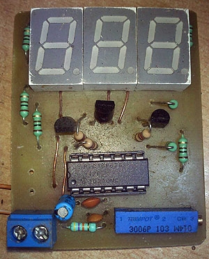 PORTA is rated for a 50 mA source current and 80 mA sink current. This makes the PIC16C71 ideal for driving 7-segment LEDs. Since the total number of I/O pins is limited to 13, the 8-bit PORTB is used to drive the 4 LEDs, while external sink transistors, or MOSFETs.
The multiplexing is achieved by turning on each LED for a 5 ms duration every 20 ms. This gives an update rate of 50 Hz, which is quite acceptable to the human eye as a steady display. The 5 ms time base is generated by dividing the 4.096 MHz oscillator clock. The internal prescaler is configured to be a divide by 32 and assigned to Timer0. TMR0 is preloaded with a value = 96. TMR0 will increment to FFh and then roll over to 00h after a period = (256 – 96) • (32 • 4/4096000) = 5 ms.
When TMR0 rolls over, the T0IF flag bit is set, and because bits T0IE and GIE are enabled, an interrupt is generated.
A 4×4 keypad can very easily be interfaced to the PIC16C71 device’s PORTB .
The internal pull-ups have a value of 20k at 5V (typical). In order to sense a low level at the input, the switch is “connected” to ground through a 2.2 kΩ resistor. A key hit normally lasts anywhere from 50 ms to as long as a person holds the key down. In order not to miss any key hits, the keypad is sampled every 20 ms (just after the update of the MSD).

 The software implements a simple timer which increments at a 1-second rate. Every second, the 4 nibbles (two 8-bit registers, MsdTime and LsdTime) are incremented in a BCD format.
The analog channels are connected through individual potentiometers to their respective analog inputs and are sampled every 20 ms in a round robin fashion. The sampling rate can be increased to as fast as once every 5 ms if required. The keypad sampling need not be any faster than once every 20 ms.
This project and source code was designed by Stan D’Souza from Microchip Technology.
For more detail: PIC16c71 four channel digital voltmeter
- What microcontroller is used in the project?
The PIC16C71 microcontroller is used. - How is the 7-segment display multiplexed?
Each digit is turned on for 5 ms every 20 ms to achieve a 50 Hz update rate. - How is the 5 ms multiplex time base generated?
By dividing the 4.096 MHz oscillator with the internal prescaler set to divide by 32 and using Timer0 preloaded with 96. - How often are analog channels sampled?
Analog channels are sampled every 20 ms in a round-robin fashion (can be increased to every 5 ms if needed). - How often is the keypad sampled?
The keypad is sampled every 20 ms. - What resistors are used with the keypad switches?
Each switch connects to ground through a 2.2 kΩ resistor and uses internal 20 kΩ pull-ups. - How is a 1-second timer implemented?
The software increments two 8-bit registers (MsdTime and LsdTime) in BCD format once per second. - Why are external sink transistors used for LEDs?
Because PORTB drives the segments but external transistors are used to sink the digit common lines due to limited I/O and current handling. - Who designed the project and source code?
The project and source code were designed by Stan D’Souza from Microchip Technology.