Summary of PIC16F84A timer0 code and Proteus simulation
This article provides C code and a Proteus simulation for using Timer0 on the PIC16F84A (HI-TECH C, MPLAB). It explains configuring OPTION_REG for a 1:2 prescaler, enabling T0IE and GIE, and how Timer0 (8-bit) overflows every 256 ticks to trigger an ISR that toggles RA0. With a 20 MHz crystal (5 MIPS), the timer overflows approximately every 102 microseconds. Download links for code and the Proteus project are provided.
Parts used in the PIC16F84A Timer0 Project:
- PIC16F84A microcontroller
- 20 MHz external crystal
- Resonator or crystal oscillator circuitry (capacitors as needed)
- LED connected to RA0 pin
- Current-limiting resistor for LED
- Power supply for PIC (Vdd and Vss)
- Proteus simulation software (for simulation)
- MPLAB IDE (v8.85 used for compilation)
- HI-TECH C compiler (v9.83)
This post provides the timer0 code for PIC16F84A microcontroller. This code is written in C language using MPLAB with HI-TECH C compiler. You can download this code from the ‘Downloads‘ section at the bottom of this page.
It is assumed that you know how to blink an LED with PIC16F84A microcontroller. If you don’t then please read this page first, before proceeding with this article.
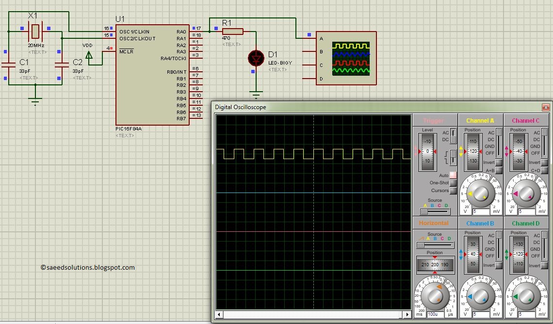
The result of simulating the code in Proteus is shown below.
In this circuit, PIC16F84A is running on external crystal of 20MHz value. RA0 pin is toggled every time timer0 expires and executes it’s ISR[1] code. In the above figure, it is clear that after approximately every 100usec, RA0 pin is toggled i-e timer0 expires. You can easily change this value in the code.
Code
The code used to initialize timer0 is shown below.
In this function, OPTION_REG is initialized to make timer0 prescalar to be 1:2. Timer0 is an 8bit timer, so it expires after reaching a value of 255. When timer0 prescalar is made 1:2 then it means that timer0 value will increment after every two clock cycles. Since PIC16F84A is running at 5MIPS[2] speed, this means that timer0 will expire after every 256*2/5 = 102 usec[3]. T0IE bit enables timer0 interrupts and GIE bit enables global interrupts.
Timer0 interrupt service routine code is shown below.
Downloads
Timer0 code for PIC16F84A was compiled in MPLAB v8.85 with HI-TECH C v9.83 compiler and simulation was made in Proteus v7.10. To download code and Proteus simulation click here.
For more detail: PIC16F84A timer0 code and Proteus simulation
- What does the provided code demonstrate?
It demonstrates initializing Timer0 with a 1:2 prescaler and an ISR that toggles RA0 on each Timer0 overflow. - How often does Timer0 overflow with the given settings?
With an 8-bit timer, 1:2 prescaler, and 5 MIPS clock, Timer0 overflows approximately every 102 microseconds. - How is the Timer0 prescaler configured?
The prescaler is set via OPTION_REG to give a 1:2 prescaler. - Which bits enable Timer0 interrupts and global interrupts?
T0IE enables Timer0 interrupts and GIE enables global interrupts. - What toggles when Timer0 expires in the example?
The RA0 pin is toggled in the Timer0 ISR each time Timer0 overflows. - What tools were used to compile and simulate the code?
The code was compiled in MPLAB v8.85 with HI-TECH C v9.83 and simulated in Proteus v7.10. - Can the overflow interval be changed in the code?
Yes, the article states you can easily change the overflow value in the code. - Where can the code and simulation be obtained?
They are available from the Downloads section linked in the article.