
Summary of Meet the Parallax Propeller QuickStart Board
The Parallax Propeller QuickStart Board simplifies learning the unique 8-core Propeller microcontroller. This board integrates the P8x32MM chip, USB interface, and EEPROM, featuring built-in LEDs and touchpads for immediate experimentation without complex wiring. The article guides users through installing Spin software, connecting via USB, and running a "Blinky" program to blink an LED on pin 16, demonstrating basic output control using the Spin language.
Parts used in the Propeller QuickStart Project:
- P8x32MM Propeller processor chip
- 64 KB EEPROM
- USB interface chip
- Voltage regulator
- Eight touch pads
- Eight LEDs
- Spin Tool Software v1.2.7
The Propeller processor chip is the most unique micro-controller on the market today.
It’s not just a single microprocessor, but EIGHT independent processors that share
resources like memory and I/O pins. And it can do some pretty amazing things that
the rest of the microcontrollers like the Ardino and PICs just plain can’t do!
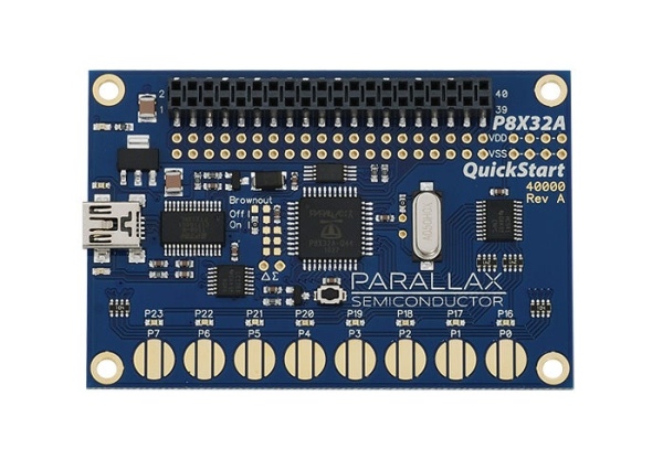
(But today, all we want to do it blink an LED)
Each of the processors (called a Cog) has 512 LONGS (32 bits each) (or 2048 bytes) of RAM
memory for it’s own use. In addition, all eight processors share an additional 64K bytes
(16K LONGS) of shared HUB memory. Hub memory is divided into 32K bytes of ROM
(from address 0 to 7FFF, or low memory) and 32K bytes (8092 LONGS) of RAM from 8000 to
FFFF hex).
The ROM section contains the boot loader code, math tables, and character fonts.
RAM is for program storage, variables and stack space.
The hub controls COG access to Propeller resources like memory or I/O pins in “round robin”
fashion. For more exciting details of the COG and HUB tune into chapter 5 of the manual and
check it out!
The programming language is called Spin, and it too is rather unique.
Today I’d like to introduce the Parallax “QuickStart” board.
This is probably the best board to buy to get started with the Propeller chip from Parallax
since it has more useful toys to play with – built in. No need to learn to wire up microelectronic
circuits just to blink an LED!
The normal (necessary) chips are on board, of course…
P8x32MM Propeller processor chip, 64 KB EEPROM, USB interface chip and voltage regulator
are all there. But this board also has, across the bottom edge, eight “touch pads” and eight LEDs
that you can play with immediately.
The Touchpads are used as input buttons. They take a bit more programming support than a regular
switch, but they cost a whole lot less (they are “printed” on the circuit board) and work pretty well.
But that’s a bit more advanced topic (the required Touchpad drivers are available on-line at the
Propeller Object Exchange)
So first off, lets, hook up and get started…
Step 1: SetUp the QuickStart Board
Physically connecting the QuickStart board to your PC is simplicity itself,
but there IS a catch.
Since this is a USB device, you MUST load the USB drivers before plugging the board’s
USB cable into your computer.
Driver and editor are downloaded from Parallax at their web site…
http://www.parallax.com/tabid/442/Default.aspx#Software
There is quite a bit of stuff there for free, but all we really need to get started is the
Propeller/Spin Tool Software.
Propeller/Spin Tool Software v1.2.7 (R2) – (Supports Windows 2K/XP/Vista/7.
Requires IE7 or newer Or FireFox 3.0 or newer)
Includes software, USB driver, Propeller Manual, PE Kit Labs text and example
code, schematics, quick reference, Propeller Help and tutorial examples.
Click the download tab, save the file to your hard drive.
Before running the setup-Propeller-Tool file, close all other programs that may be
running on your computer.
Then click on the setup program and follow the instructions. Pretty normal stuff.
Personally, I install to a custom folder – C:\Prop – instead of the default in the
Program Files folder. It’s a lot easier to get to and spell(!)
When the setup program finishes, you are all ready to get going.
Step 2: Connecting the QuickStart Board to Your Computer
It’s USB. Just plug it in.
Listen for the two-tone sound that indicates Windows found the device and
watch for the notice that it has located and identified the board.
Also the red and blue LEDS on the QS board (that show communication
Read/Write) will blink as the QS and your computer meet and shake hands.
That’s it.
If there are problems,
(usually because somebody plugged in the board before the drivers were loaded)
check Control Panel/system/hardware/device manager page for unrecognized USB devices.
Remove any Xed out devices and reinstall the drivers..
T H E N plug the QuickStart USB cable into your computer. 🙂
Step 3: Programming!
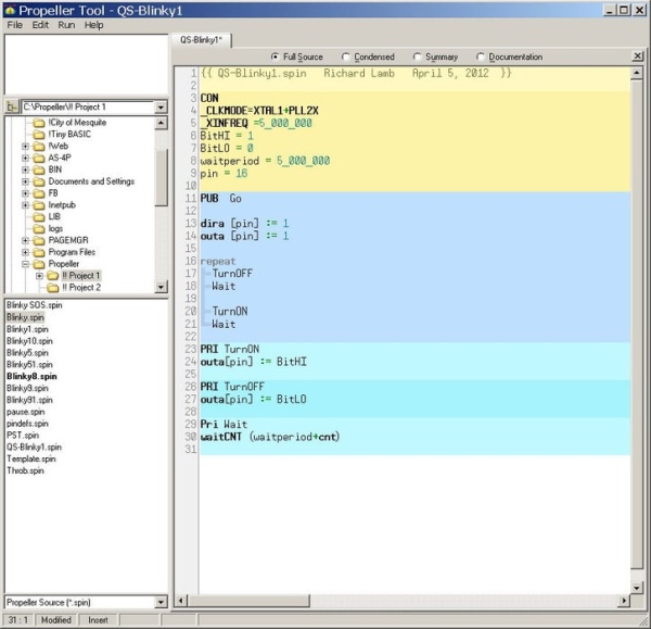
Start the Spin Tool.
Start/All programs/Parallax/Spin Tool should be there now.
(But it’s even easier if you have the shortcut icon on your desktop)
On the left are several important parts –
a browser to let you locate folders on your computer,
and a list of what files are in the selected folder.
Blinking an L.E.D. is the micro controller equivalent of “Hello World”.
So that’s where we start…
I have selected Blinky.Spin as an example, which is loaded into the work area
on the right.
The top line (light yellow) is a comment,
The yellow section is CONSTANT DECLARATIONS.
The first blue section is out main program,
The rest are PRIVATE functions to support that program.
(the colors appear as you declare each section)
CON – CONstants
Sets the system clock speed and mode, and declares several constants.
The values assigned to these words can not be changed by your program.
VAR – VARiables
We don’t have any variables defined for this program, so there is no VAR section.
PUB – PUBlic code block
Spin uses the first code block as the starting point.
This one is named “Go”
The program blinks an LED attached to pin 7
So Pin 7 direction is set as output (dira [pin] :=1),
and a zero written to that pin (outa [pin] := 1).
A zero means low voltage appears on the output pin.
Writing a one to that pin makes the voltage on the output pin go “high”
repeat starts an infinite loop – runs forever – or until the program is changed.
In other words, a loop.
Notice the indentation!
This is the way that you tell Spin how the program is “structured”.
It’s VERY IMPORTANT.
This program will repeatedly (and in order) calls the PRIvate functions –
TurnOff, Wait, TurnOn, and wait.
Step 4: Running QS-Blinky1.Spin
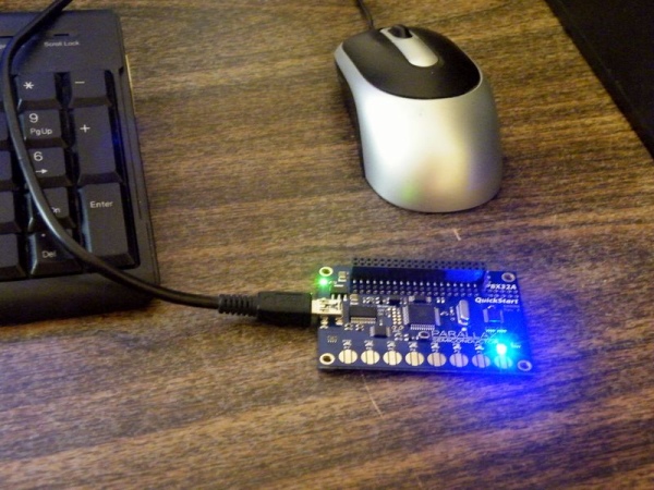
If you were to type this program in (absolutely as shown here) and RUN it,
(Run/Compile Current/Load Ram – or just press F10)
you would be rewarded by seeing the LED on pin 16 (right most LED on the
QuickStart board)
BLINK!
On and off and on and off and…
Well, maybe that doesn’t sound like the most exciting program ever written.
it’s certainly not a monster robot ready to invade Earth (yet).
But it’s where it all starts…
Source: Meet the Parallax Propeller QuickStart Board
- What is the main advantage of the Propeller processor?
The Propeller chip features eight independent processors that share resources like memory and I/O pins. - How many Cogs does the Propeller processor have?
The processor contains eight independent processors called Cogs. - Can I use the QuickStart board to blink an LED without external wiring?
Yes, the board has eight LEDs built in so you do not need to wire up microelectronic circuits. - What must be done before plugging the USB cable into the computer?
You must load the USB drivers from the Parallax website before connecting the device. - Which programming language is used for the Propeller chip?
The programming language is called Spin. - Where is the boot loader code stored on the board?
The boot loader code is located in the ROM section of the shared HUB memory. - What happens if the board is plugged in before drivers are installed?
The system may show unrecognized USB devices that require driver reinstallation. - Which key combination compiles and loads the program in the Spin Tool?
Pressing F10 runs the compile current and load ram commands. - On which pin does the example Blinky program activate the LED?
The example program blinks the LED attached to pin 16.
