Summary of USB IO Board PIC18F2455 / PIC18F2550 using pic microcontoller
USB IO Board is a USB-powered PIC18F2455/PIC18F2550 development board providing 16 I/O pins, USB-to-serial connectivity (appears as COM port), and up to 500 mA supply for projects. It is breadboard compatible, supports Windows/Mac/Linux, and is controlled via simple serial commands or the provided USB IO Board Controller (C#/VB.NET source included). Typical uses include relay control, data logging, meters, and motor/servo control. Drivers and examples show setup, command syntax, and sample routines for digital I/O and analog measurement.
Parts used in the USB IO Board:
- PIC18F2455 or PIC18F2550 programmed microcontroller (MCU)
- USB Type B Connector
- 20MHz Crystal Resonator
- 2x 10K Resistors (brown black orange gold)
- 470 Ohm Resistor (yellow purple brown gold)
- 470nF Ceramic Capacitor
- 100nF Ceramic Capacitor
- 12-pin header (for breadboard/bottom side)
- 8-pin header (for breadboard/bottom side)
- 5-pin ICSP header (In Circuit Serial Programming)
|
|
About PIC18F2455 / PIC18F2550 USB IO Board
USB Input / Output Board is a spectacular little development board / parallel port replacement featuring PIC18F2455 / PIC18F2550 microcontroller. USB IO Board is compatibile with Windows / Mac OSX / Linux computers. When attached to Windows IO board will show up as RS232 COM port. You can control 16 individual microcontroller I/O pins by sending simple serial commands. USB Input / Output Board is self-powered by USB port and can provide up to 500mA for electronic projects. USB IO Board is breadboard compatible. Simply solder included 12-PIN & 8-PIN headers on the bottom side of the PCB and the board can be plugged into a breadboard for quick prototyping.
|
These are examples of what can be built using USB IO Board |
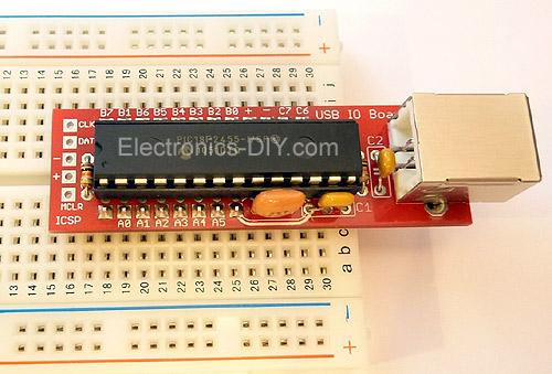
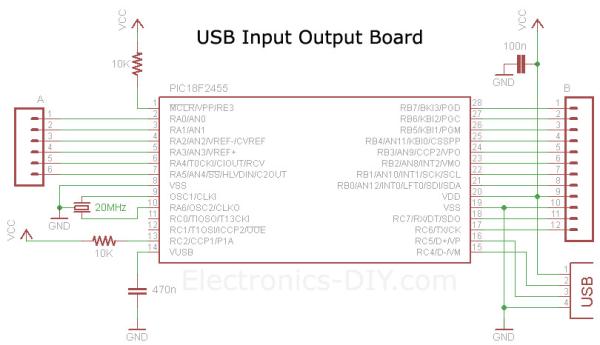
C1 470nF capacitor
C2 100nF capacitor
5-PIN header on the left is an ICSP connector (In Circuit Serial Programming) for downloading future firmware releases.
Download USB IO Board drivers and unzip it.
2) Connect USB IO Board to a computer using standard USB cable.
3) Windows will ask you if you want to install a driver. Point it to drivers you unzipped.
Windows 2000 / XP
Under Windows 2000 or XP you will be prompted twice to install two drivers. On the first prompt please browse and point to MCHPUSB driver folder. On the second prompt please browse and point to USB CDC driver folder.
Windows 7 / VISTA
Under Windows 7 or VISTA you might be only prompted once to install USB CDC driver if MCHPUSB driver is already installed.
4) After the drivers are installed go to the Device Manager (right click on My Computer and click Properties->Hardware->Device Manager), and look under the Ports (COM & LPT) section, and you should see a new serial port there. Note the COM port number.
5) Open up your favorite serial emulator; the really awful HyperTerminal that comes with Windows, or my personal favorite USB IO Board Controller which can be downloaded here.
6) After launching USB IO Board Controller select the COM port from the drop-down list to connect to the board, type “V” in the input box and hit Enter or click on “Send” button. You should get back a firmware version number from PIC18F2455 / PIC18F2550 chip. This proves that USB IO Board is working properly. Now you are ready to learn about the commands that can be used to control USB IO Board.
USB IO Board can be controlled with just about any serial port emulation program such as Hyper Terminal that comes with every Windows OS. The problem with Hyper Terminal is that you can’t see the commands as you type them and that could be very annoying. With Hyper Terminal you also have to go through the wizard for setting up a serial port connection, and if the COM port changes you pretty much have to do it over and over again.
Luckily we have released our own little application called USB IO Board Controller that is so much easier and fun to use than Hyper Terminal. It only takes 25KB of space so it’s very lightweight. USB IO Board Controller will also show you COM port of USB IO Board so that will save you the trip (and time) to Device Manager to find out USB IO Board COM port number.
To use USB IO Board Controller select the COM port from the drop down list, type the command and hit “Enter” key (or click on Send button). Each command returns “OK” message to acknowlege that the command was received and processed successfully.
Download USB IO Board Controller (Win 2K, XP, VISTA, Win7)
Note: If you try to execute USB IO Board Controller and it doesn’t work you will need to download and install
Microsoft .NET Framework 3.5
Below you will find USB IO Board Controller source code written in C# and Visual Basic .NET using free Visual Studio 2008 Express IDE software. Use it as a foundation to get started on any projects of your choice. The code demonstrates how to list COM ports, connect to COM port, send commands and receive data from USB IO Board.
USB IO Board Controller – C# Source Code
|
| Lets run some sample commands to see how easy it is to turn LED ON/OFF. Connect LED to microcontroller; longer leg to PIN28 (RB7), shorter leg to ground (GND) via 470 Ohm resistor. Now, to turn LED ON and OFF type these commands using USB IO Board Controller. Remember to hit “Enter” key after each command is entered.Configure Port A, B and C as outputs: C,0,0,0,0Turn LED ON (+5V): PO,B,7,1Turn LED OFF (0V): PO,B,7,0 Here’s an example on how we can measure voltage on PIN2 (AN0) and still be able to use other ports as outputs. Maximum input voltage of PIC18F2455 / PIC18F2550 microcontroller is limited to 5V but with a simple two resistor voltage divider we can easily measure up to any voltage we want. Use 1K resistor connected to PIN2 and GND and 100K resistor connected to PIN2 and input to measure up to 500V. Please see USB Voltmeter page for more information. Configure Port A – PIN2 as analog input, B and C as outputs: Sample input voltage on PIN2: USB IO Board will return digital representation of voltage and display it on the computer. Turn LED ON on PIN28 (+5V): Turn LED OFF on PIN28 (0V): Please read more about “C” command below on how to configure more analog inputs. |
Notes for ALL commands:
|
For more detail: USB IO Board PIC18F2455 / PIC18F2550
- What microcontroller is used on the USB IO Board?
The board uses a programmed PIC18F2455 or PIC18F2550 microcontroller. - How is the USB IO Board powered?
The board is powered by the USB port at 5V and can provide up to 500mA. - How many I/O pins are available on the board?
The board provides 16 individual microcontroller I/O pins. - What connector is used for USB on the board?
The board uses a USB Type B connector. - Can the USB IO Board be used with Windows?
Yes, it is compatible with Windows and appears as an RS232 COM port after drivers are installed. - How do you turn an LED on and off using the USB IO Board?
Connect LED to PIN28 (RB7) with a 470 Ohm resistor to GND, then send PO,B,7,1 to turn ON and PO,B,7,0 to turn OFF. - What software can be used to control the board?
You can use standard serial emulators like HyperTerminal or the provided USB IO Board Controller (with C# and VB.NET source). - How do you configure analog input on PIN2 (AN0)?
Use the C command to configure Port A PIN2 as analog input, for example C,1,0,0,1 to set A as analog and B and C as outputs. - What is the command termination requirement?
Each command must be terminated with CR or LF or a combination of the two to be valid. - Is there a size limit for commands sent to the board?
Yes, each command including the terminating CR must be 64 bytes or less.