Summary of Thermistor Respiratory Monitor
The project builds a low-cost respiratory monitor for resource-constrained settings using a mask-mounted thermistor, MCU-based ADC sampling, signal amplification and filtering, an analog comparator for breath timing, LCD display, and audible alarms for apnea and low battery. It emphasizes power efficiency, rapid capacitor charging at startup, and software filtering to compute breaths per minute and manage alarms.
Parts used in the Respiratory Monitor:
- AtMega1284p microcontroller
- NTHS0402 thermistor (Vishay Dale)
- Operational amplifier (Op Amp)
- Resistors (1 kΩ, 10 kΩ, 30 kΩ, 100 kΩ, 330 Ω, 3 kΩ, etc.)
- Capacitors (2200 µF, 220 µF, 1 nF, others)
- Piezoelectric speaker
- Vartronix MDL(s)-16264 LCD
- 10 kΩ trimpot (LCD contrast)
- Push-button for LCD activation
- Voltage divider components for battery measurement
- 9 V battery (or AC power supply option)
- Nebulizer mask (standard, used to house thermistor)
The concluding assignment in ECE 4760 involves the creation of a respiratory monitor tailored for use in resource-constrained settings. This device determines a patient’s respiration rate by identifying temperature fluctuations as the patient breathes through a mask. Notable attributes of this device encompass an alarm mechanism activated by a piezoelectric speaker, which triggers when the patient’s breathing ceases. Additionally, it includes a low-battery indicator, signaling when the device’s battery voltage reaches a predefined threshold.
Motivation
For our project, we aimed to address a real-world issue. Many biomedical devices, including commonly available respiratory monitors, are designed with the developed world in mind and rely on a consistent power supply for their operation. We aspired to create a solution that could adapt to diverse environmental conditions.
Our device integrates several principles we’ve learned not only in this semester’s ECE 4760 course but also from other courses at Cornell. We utilize analog-to-digital conversions to sample data from both the thermistor and the battery, pulse-width modulation to produce a signal for the speaker, and timers to manage task switching. Our implementation also includes a range of analog circuitry for voltage regulation and signal amplification. Crafting a dependable and precise respiratory monitor presented us with challenges, yet the experience proved to be highly rewarding.
Previous Work
During our research for this project, we encountered various respiratory monitors employing different sensors for tracking breathing patterns. Alternative methods of monitoring respiratory rate include a chest force sensor, which detects chest movement-induced force, an impedance pneumograph that employs skin electrodes to assess transthoracic impedance, and pulse oximetry, which measures blood oxygen saturation. While commercial devices for respiratory rate monitoring are available, they often utilize motion or force sensors to estimate respiration rate. These devices are typically better suited for use in developed regions with stable power supplies. Our objective, however, was to create a device tailored to the requirements of underdeveloped areas. Therefore, we aimed to design our thermistor-based monitor to be more cost-effective, user-friendly, and reliable.
Furthermore, during our research, we came across another project involving a thermistor-based respiratory monitor. The design of this device varied from ours, as it featured two thermistors: one placed in the external environment for reference and another inserted into the nostril.
High-Level Block Diagram
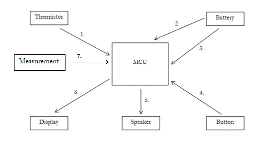
1. Thermistor Readings
As the surrounding temperature increases, the thermistor’s resistance decreases, and conversely, it rises as the temperature decreases. The voltage exhibits corresponding changes, decreasing as a person exhales and increasing during inhalation. We employ an operational amplifier to amplify these temperature fluctuations. The amplifier’s output is then directed to the microcontroller’s ADC channel 0.
2. Voltage Assessment
During battery operation, our device periodically samples the voltage across the battery approximately every minute. Given that our device utilizes a 9V battery, we implement a voltage divider to reduce the voltage to around 2.2V at PINA1 (ADC channel 1).
3. Power Source
Our device can be powered either through a standard AC power supply or a single 9V battery.
4. Display Activation
To conserve power, the user is required to press and hold a button to activate the display and access the respiration rate reading. This precaution prevents accidental battery drain caused by leaving the display on.
5. Audible Alerts
Our device incorporates two distinct alarms, generated through a piezoelectric speaker. The first alarm emits a higher-pitched continuous sound when the patient is not breathing. The second serves as a low-battery warning, producing a one-second long tone.
6. Respiration Rate Presentation
The device calculates the breathing rate and presents it in breaths per minute on an LCD screen. This feature enables the individual monitoring the patient to assess whether their breathing rate is excessively rapid or slow.
7. Measurement Process
This function performs the actual calculation of the respiration rate using samples obtained from ADC0.
Design Decisions
Microcontroller Selection
When it came to selecting an appropriate microcontroller for our project, our initial intention was to find the most compact microcontroller feasible to mount directly onto the device’s mask. However, as we evaluated the number of required I/O ports and ADC channels for our project, it became evident that the AtMega1284p microcontroller, which we had been utilizing throughout the semester, was the ideal choice.
Thermistor Consideration
In the early phases of project design, we conducted experiments involving various thermistors and their placement on the device. Given that human respiration doesn’t yield a significant temperature variation, our aim was to identify the smallest and, consequently, the most sensitive thermistor available. Larger thermistors that we tested either failed to detect a “breath” or exhibited a notably slow response time. Additionally, we determined that placing the thermistor within a mask encompassing the patient’s nose and mouth was the least intrusive option.
Display Choice
As we aimed to create an energy-efficient device, selecting the appropriate display for respiratory rate readings became a key consideration. Originally, we intended to use two 7-segment displays that would activate when the user pressed a button. However, we opted for an LCD screen to provide a more visually appealing display. To reduce power consumption, the LCD screen only receives power when the user activates the display button, thereby lightening the load on the battery.
Regulatory Compliance
In its capacity as a medical device, our respiratory monitor must adhere to the regulatory standards mandated by governments. This encompasses compliance with HIPAA regulations, which safeguard individuals’ medical records and other sensitive health-related information, including respiration rate data. Nevertheless, given that we do not intend to store this information, compliance with this regulation should not pose an issue. Prior to potential commercial distribution in the United States, the device would also necessitate FDA approval.
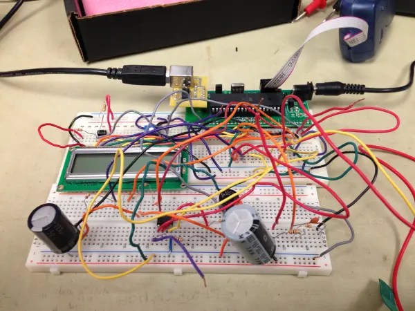
Hardware Design & Implementation
To enable the respiratory monitor’s functionality, six distinct hardware components are required. These components are presented below in the order of their listing:
1. Thermistor Reading
2. Thermistor Signal Enhancement
3. Analog Comparator
4. Capacitor Charging Circuit
5. Activation Button for LCD Display
6. Battery Status Monitor

1. Thermistor Measurement
We employed a thermistor-based measurement system for tracking patients’ respiration rates. This thermistor is situated within a mask worn by the patient, which is a standard nebulizer mask utilized by asthma patients. The thermistor is positioned inside the mask, directly in front of the patient’s mouth. When the patient breathes, the warm air from their breath causes the resistance (Rth) of the thermistor to vary. Consequently, the voltage across the thermistor (Vth) also undergoes proportional changes in accordance with the patient’s breathing patterns. Hence, we can utilize Vth as an indirect indicator of the patient’s respiration. To monitor Vth, we adopted a voltage divider, depicted in Figure 1.
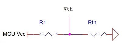
At room temperature, the thermistor registers an approximate resistance of 1.2 kΩ. Consequently, we opted for R1 with a value of 1 kΩ. This choice was deliberate, aiming to maintain Vth at around 2.5 V in the absence of any breath on the thermistor. Our intention was to establish 2.5 V as the baseline voltage for when no breathing is detected, allowing our device to identify significant inhalations or exhalations.
2. Thermistor Amplification
We selected the NTHS0402 thermistor from Vishay Dale for our project. This particular thermistor boasts an impressively short thermal time constant of 5 seconds, rendering it exceptionally sensitive. Through experimentation, we discovered that the voltage change resulting from a person’s breath interacting with the thermistor was around 10 mV. Recognizing that this change was too minuscule to be practical, we opted to amplify it using an Op Amp in conjunction with a high-pass filter.
Employing just an Op Amp would be insufficient because it would amplify the entire signal, whereas our aim was to solely amplify the voltage change. Our literature research indicated that the average breathing rate for an adult male ranges from 15 to 20 breaths per minute, while for an infant, it’s between 30 and 60 breaths per minute. We set the slowest desired period at about 4 seconds.
To achieve this, we selected a time constant of 22 seconds for our high-pass filter. This configuration means that the Op Amp will amplify any signal with a period less than 22 seconds. Our choice of 22 seconds enables our device to detect both hyperventilation and regular breathing patterns. To establish the 22-second time constant, we set R2 to 10 kΩ and C1 to 2200 µF, as illustrated in Figure 2. We further adjusted the gain to 4 by selecting R3 to be 30 kΩ.
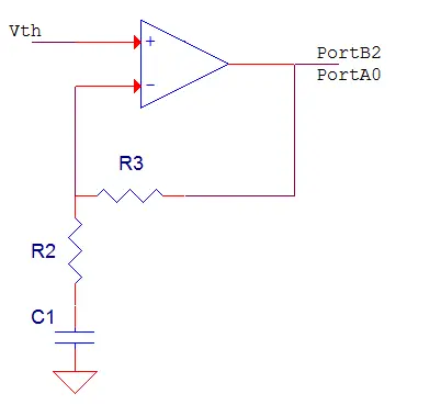
The circuit’s output is directed to both PortA0 and PortB2. PortA0 serves as the input for the ADC, while PortB2 acts as the positive reference pin for the AC, as explained in the software design section.
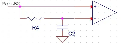
3. Analog Comparator
The respiratory rate is determined by employing an analog comparator (AC) to compare the amplified voltage derived from the thermistor with a reference voltage. Given that the respiratory signal closely resembles a sine wave with a DC offset, we opt to position the reference voltage at the DC offset level. However, it’s important to note that patients of different age groups exhibit varying steady-state breathing temperatures. For instance, older patients expel hotter air during exhalation compared to younger patients. Consequently, the DC offset for older patients will be lower than that for their younger counterparts.
To automatically ascertain the appropriate reference voltage for a patient, we incorporate a low-pass filter illustrated in Figure 3. This low-pass filter boasts a time constant of 22 seconds, effectively filtering out the signals of interest. As the filter rejects the respiratory signal, its output equates to the average value of the incoming signal. Given that the incoming signal mirrors a sine wave with a DC offset, the average value corresponds to the DC offset. The output of this filter is then directed to the voltage reference pin of the AC, as depicted in Figure 3.
The respiratory signal is sourced from PortB2 and feeds into both the filter and the positive voltage pin of the AC on the microcontroller unit. To achieve a 22-second time constant, we set R4 to 100 kΩ and C2 to 220 µF.
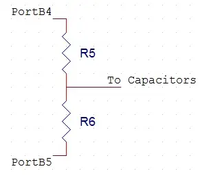
4. Capacitor Charger
The time constant for the thermistor amplification circuit detailed earlier is set at 22 seconds, signifying that it takes several minutes for the capacitor to reach a full charge. This extended charging duration impairs the device’s proper functioning since the capacitor remains incompletely charged during this time.
To expedite the charging process, we introduced an additional circuit featuring a smaller resistor. This adjustment results in a quicker charging time. The schematic for the charging capacitor is depicted in Figure 4 below. When PortB4 is set to 5 V and PortB5 to 0 V (further elaborated in the software design section), the capacitor initiates its charging process through R6. Both R5 and R6 are configured at 330 Ω to minimize resistance. Consequently, the time constant for charging is reduced to 0.73 seconds, and the overall charging duration is approximately 6 seconds. R5 serves the crucial function of protecting PortB4 from potential damage.
5. LCD Display Button
To conserve power, a button must be held down by the user to activate the LCD. This approach ensures that the LCD remains off when not in use, preventing accidental activation. This functionality was achieved by linking the LCD’s Vcc pin to the MCU’s Vcc via a push button, as depicted in Figure 5. When the button is pressed, the LCD’s Vcc pin is supplied with 5 V. Resistor 10 and Resistor 7 are employed to maintain the voltage at the pink node below the threshold voltage of the MCU pins. Consequently, PortB1 will register 0 V when the button is not pressed and 5 V when the button is pressed. Both R10 and R7 have values of 330 Ω.
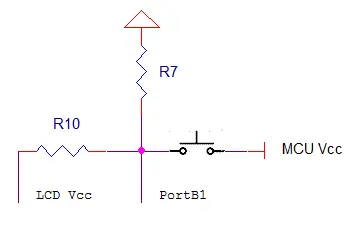
We utilized the Vartronix MDL(s)-16264 LCD in conjunction with a 10 kΩ trimpot for contrast adjustment.
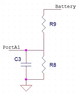
6. Battery Monitor
We employed a voltage divider in conjunction with a low-pass filter, as depicted in Figure 6 below, to gauge the voltage of the 9 V battery. The voltage divider’s function is to transform the voltage range from 0-9 V into 0-5 V, safeguarding the MCU from potential damage. Subsequently, the ADC is utilized to convert the analog voltage into a digital format, enabling the MCU to analyze it. The low-pass filter serves the purpose of filtering out any high-frequency signals that may be present. This is achieved by configuring C2 to 1 nF and R8 to 1 kΩ, resulting in a filter time constant of 1 µs. Additionally, R9 is set to 3 kΩ, causing the voltage divider to produce an output that is one-quarter of the original voltage.
Software Design & Implementation
Software Overview
The MCU was programmed with the AVR Studio version 4.15 using the C programming language and compiled with the WINAVR GCC C compiler. The software for the respiratory monitor comprises 5 distinct tasks and 2 interrupt service routines (ISR). The first ISR, known as the Timer0 Compare Match Vector, triggers every 16.4 ms and reduces three separate timeout counters each time it’s triggered. Additionally, it resets the count variable (used to track respiration rate) to prevent it from overflowing. Given that the MCU’s clock runs at 16 MHz, we configured the prescaler to 1024 and set OCR0A to 255. This configuration causes the ISR to activate every 256 clock cycles. The second ISR, the AC ISR, triggers when the onboard AC produces an output of 1. This ISR is employed to calculate the person’s respiration rate, which will be explained in more detail in the relevant section.
Main
The primary role of the main function is to initialize the device and subsequently enter the main loop. Notably, the low pass and high pass filters are equipped with extensive time constants of 22 seconds, resulting in a significant delay before the entire device becomes operational. This startup time, lasting several minutes, was deemed excessively long. To address this issue, we designed a distinct circuit dedicated to rapidly charging capacitors with considerably shorter time constants. This modification is executed within the initial ten lines of code in the main function, prior to the initialization of any other processes.
To begin, PinB5 and B4 are configured as output pins, with B5 set to 0 V and B4 to 5 V. This essentially activates the Vcc and ground for the charging capacitor circuit. The charging capacitor circuit remains active for 5 seconds before being deactivated by switching B4 and B5 to input mode. Subsequently, the initialization functions are activated, and the main loop, denoted by “while(1),” commences.
Within the while-loop, a series of conditions are checked to determine whether the device should execute specific tasks. The thermistor and sampling tasks are both time-driven, with the timer count resetting and the corresponding task initiated when their respective timers reach zero. The thermistor sampling task occurs every second, while the battery sampling task is executed at minute intervals. The measure task is initiated when the measure_flag signals that a measurement is ready to be taken. Lastly, the display task is triggered when the user presses and holds down the display button.
Thermistor Sampling
The thermistor samples are acquired via PINA0. Initially, the ADMUX register is configured to enable left-adjusted results and an external reference. The microcontroller (MCU) then awaits a conversion and updates the variables ‘sample_old’ with the current sample and ‘sample’ with the high bits from the ADC. The absolute difference between ‘sample_old’ and ‘sample’ is utilized to detect a cessation of breathing. When this difference is less than or equal to 8, it’s categorized as a “no breath” event. If the MCU detects 10 consecutive “no breaths,” it triggers a PWM signal to activate the speaker. If the difference exceeds the tolerance, the “no breath” counter ‘c’ resets to 0, and the PWM signal is turned off.
The tolerance for breath difference was determined through experimentation. Analyzing ADC values on the UART, the sampled values ranged between 6 and 8 when a person wasn’t breathing. To account for this variation, we compare consecutive thermistor samples against a threshold of 8 rather than 0. Additionally, a counter is used to keep track of the number of “no breath” instances detected. This is essential because consecutive samples might fall within the tolerance range depending on an individual’s breathing pattern. Counting up to 10 consecutive “no breaths” significantly reduces the occurrence of false positive alarms.
The concepts of ADC sampling and PWM signal generation were previously covered in Labs 2 and 3 earlier in the semester.
Battery Sampling
In order to obtain a battery sample, the MCU activates ADC channel 1 by configuring PINA1 through the ADMUX register. The MCU patiently waits for the conversion to complete, and afterward, it records the high bits of the ADC into the ‘bat_samp’ variable. This sample is then compared to the ADC value corresponding to a 7.6 V voltage level, as it was observed during testing that the device becomes unstable at 7.5 V. Consequently, we decided to alert the user when the battery voltage reaches 7.6 V.
If the battery sample falls within or below the defined tolerance, a PWM signal is generated. It remains active for approximately 1 second and is then deactivated. The PWM channel responsible for producing a tone as a low-battery warning employs a larger prescaler compared to the channel used for the alarm when the patient isn’t breathing. This difference in prescaler values results in the low-battery warning tone having a lower pitch.
Measuring Task
The respiratory rate is determined by utilizing the AC (Analog Comparator) and measuring the time interval between when the voltage across the thermistor crosses the reference voltage. The initial phase of this process occurs within the Interrupt Service Routine (ISR). When the voltage across the thermistor crosses the reference voltage threshold, the AC ISR is triggered. Subsequently, it records the number of clock cycles into the variable ‘tau2’ at the current crossing and retains the number of clock cycles from the previous crossing in ‘tau1.’ The difference between ‘tau2’ and ‘tau1’ is then stored in the variable ‘period.’ Essentially, this ISR calculates the discrepancy in clock cycles between two consecutive reference voltage crossings. After this measurement, the ‘measure’ flag is set, initiating the ‘measure’ task.
In the ‘measure’ task, an average difference in clock cycles is computed by performing a weighted average between the newly measured cycle difference and the previous average cycle difference. The weights used are 0.75 for the previous average and 0.25 for the new difference. This weighted average is calculated to derive an average respiratory rate. The average cycle difference is then converted into a respiratory rate in breaths per minute (bpm). This conversion is achieved by transforming the cycle difference into minutes and taking the reciprocal, as the AC ISR is activated for each breath, effectively measuring the time for one breath.
During the development of this code, a challenge arose where the AC ISR was triggering multiple times for a single crossing. This was occurring because, as our signal crossed the reference voltage, system noise caused the signal to cross the reference voltage multiple times. To address this issue, when the AC ISR is initially triggered, the first line of the ISR deactivates the AC ISR and sets a flag named ‘flag.’ Subsequently, in the main program, there’s an ‘if’ statement that checks if ‘flag’ is set to 1. If it is, a 10 ms delay is introduced, after which the AC ISR is reactivated, and the ‘flag’ is reset. The 10 ms delay is implemented to ensure that the signal crosses the reference voltage threshold sufficiently, minimizing interference from noise.
Display Task
The display function serves to showcase the respiratory rate on the LCD screen when the user presses and holds the LCD push button. This functionality was accomplished by having the display function kick in when PinB1 registers as 1. When PinB1 is in the 1 state, the LCD is initialized, and the respiratory rate value stored in the ‘breathrate’ variable is transferred to the LCD buffer. Subsequently, this value is presented on the LCD screen.
- How does the device detect respiration?
It measures temperature-induced voltage changes from a mask-mounted thermistor, amplifies the signal, and uses an analog comparator and ADC sampling to detect breaths. - Can the device run on battery power?
Yes, it can run on a single 9 V battery or a standard AC power supply. - What triggers the apnea alarm?
If 10 consecutive thermistor samples show differences less than or equal to 8 (no breath), the PWM-driven piezo speaker alarm is activated. - How is low battery indicated?
The MCU samples the battery via ADC channel 1 and emits a one-second low-pitch tone when the measured voltage falls to the threshold corresponding to about 7.6 V. - How is power conserved for the display?
The LCD only receives Vcc when the user presses and holds the display push-button, keeping it off otherwise. - How is the respiration rate computed?
The analog comparator triggers on reference crossings, the ISR measures clock cycles between crossings, and the software computes a weighted average to convert period into breaths per minute. - How does the device set the comparator reference voltage?
A low-pass filter with a 22-second time constant produces the DC offset of the amplified signal and provides the reference voltage to the analog comparator. - How are small thermistor signal changes amplified?
An op amp with a high-pass filter (22 s time constant) and gain of 4 amplifies the roughly 10 mV breath signal. - How is the slow startup due to long time constants addressed?
A capacitor charging circuit with low-value resistors is enabled at startup to rapidly charge capacitors, reducing effective startup time to about 5–6 seconds before normal operation.