
Summary of Digital Oscilloscope using PIC16F688
This project details a low-cost digital oscilloscope capable of sampling four channels at 100kHz for approximately $40. It utilizes five PIC 16F688 microcontrollers, with one master coordinating four slave units to acquire data via analog-to-digital pins. A PC application built on the Processing platform serves as the user interface, displaying graphs and managing configuration through a USB-to-serial bridge (UM232R). The system supports hardware or manual triggering and stores up to 240 data points depending on channel count.
Parts used in the Digital Oscilloscope:
- PIC 16F688 microcontroller
- PC running Processing software
- UM232R USB-to-Serial chip
- Analog-to-digital pins
- Cocked LED indicator
- Trigger button
- Active memory storage
Far and away my most ambitious project to date, this
digital oscilloscope can sample up to four channels
at a rate up to 100kHz. And the best part? It only
cost me about $40 in components.
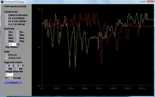
The user interface is an application running on a
PC. The user selects the configuration settings
here. When the data has been acquired, it is
displayed as a graph on this screen.
The board uses five PIC 16F688 microcontrollers,
four to sample the different channels on regular
analog-to-digital pins and communicate as slaves to
the master microcontroller. The master
communicates with the PC hosting the user interface
and configures the slaves. When the measuring is
done, the master coordinates the reporting of the
measured values to the PC.
The triggering event can be selected as any of the
channels passing any threshold voltage either rising or
falling. Alternately, it can be manual – the user pressing a
button to start the sampling. Whichever chip is designated
as the trigger starts sampling as soon as it is configured. If
the precondition to the trigger event is true (e.g. The
trigger is the voltage falling through 3V and we’re above 3V
now), the trigger chip lights the “Cocked” LED indicating the
trigger can happen at any time. Once the trigger event has
happened, the trigger chip pulls the Trigger line low.
The Trigger line going low is the indication to the master
chip to start the Clock line. The master bringing this line
high and low keeps the time for all of the chips to take
readings.
The chips can each listen to a different channel at the
same time, or they can take turns listening to the same
channel. To get the full speed, I found the only option was
to store the values in active memory – saving them took too
much time. So the limit is 80 data points for 3 or 4
channels, 160 data points for 2 channels, or 240 data
points for 1 channel. This suffices for me right now.
I started the first work on this project about
a year ago. Surprisingly the biggest
challenge was a platform on the PC that
would let me open the serial port! The
board actually uses a chip to replicate a
serial port over USB (UM232R from FTDI)
but it’s a serial port as far as the PC is
concerned. I found that Java didn’t
support this anymore, though I could find
files online, I couldn’t get it to work and
from the posts I read, this was a common
problem. I found several options for
buying serial port drivers for MS Excel, but
I objected to paying. I finally found my
solution in Processing, a tool out of MIT
and based on Java (http://processing.org/)
It’s a little flaky so there are some
work-arounds in my code, but it does the
job and it was free.
For more detail: Digital Oscilloscope using PIC16F688
- What is the maximum sampling rate of this oscilloscope?
The device can sample up to four channels at a rate of 100kHz. - How many microcontrollers are used in the board design?
The board uses five PIC 16F688 microcontrollers, consisting of one master and four slaves. - Can I use Java directly for the PC user interface?
No, standard Java does not support opening the serial port for this specific setup; the author used Processing instead. - What is the best way to trigger the sampling process?
Triggers can be set to detect voltage threshold changes on any channel or initiated manually by pressing a button. - How many data points can be stored for four channels?
The system stores a limit of 80 data points when using three or four channels. - Does the master chip control the timing for all chips?
Yes, the master chip starts the Clock line to keep time for all chips to take readings simultaneously. - Why was active memory required for storing values?
Active memory was necessary because saving values took too much time otherwise. - What component replicates the serial port over USB?
A UM232R chip from FTDI is used to replicate the serial port over USB.
