


Summary of Implementing Smart Cooling Control for Induction Heaters with PIC Microcontrollers
Summary: A PIC microcontroller-based smart cooling control system for induction heaters combines temperature sensing, intelligent PIC-driven control (ADC, PWM, GPIO), and power drivers (MOSFETs/relays) to manage fans or pumps. Using threshold, PID, or tiered strategies, it provides closed-loop cooling, safety interrupts, fault detection, HMI, and optional communications for reliable, efficient thermal protection and integration.Parts used in the Smart Cooling Control System for Induction Heaters:
- PIC microcontroller (PIC16F or PIC18F family)
- NTC thermistors or digital temperature sensors
- Analog-to-Digital Converter (ADC) (built into PIC)
- PWM-capable outputs (hardware PWM in PIC)
- General-Purpose Input/Output (GPIO) pins (on PIC)
- MOSFETs or relays for driving fans and pumps
- DC fans (for air cooling)
- Water pump (for liquid cooling)
- Timers and Watchdog Timer (built into PIC)
- LCD display or LEDs for HMI
- Input devices: tactile buttons or rotary encoder
- Communication interfaces: UART or I2C (optional)
- Resistors, connectors, and supporting PCB components
Simply put, this heat must dissipate effectively. Otherwise, critical components—IGBT power modules and the induction coils themselves—risk damage from overheating. The consequence? Expensive operational halts and diminished output.
Traditional fixes, like basic thermostats or manual cooling control, often fall short. They react too slowly, lack efficiency, and struggle with complex operating conditions.
Enter the smart cooling control system. This intelligent approach becomes essential for reliable operation. And the PIC microcontroller? It serves perfectly as the core intelligence. Why? PICs offer an unbeatable mix: great value, rich features (built-in ADC, PWM, plenty of I/O), and rock-solid reliability.
This post kicks off exploring how we design and implement an efficient, smart cooling control system for induction heaters using PIC microcontrollers. It's key to unlocking peak performance and longevity.
The Core System - Three Pillars of Smart Cooling Control
Building a reliable smart cooling system for high-power induction heaters isn't magic; it's smart engineering built on three essential, interconnected layers. Think of it like a living organism: you need senses to detect problems, a brain to make decisions, and muscles to take action. Our PIC-based control system works exactly this way, combining precise sensing, intelligent processing, and robust execution to keep temperatures perfectly in check.
Pillar 1: The "Senses" - Temperature Sensing Network
The first pillar is the sensing layer, which serves as the "eyes" of the system. It gathers real-time data about the operating temperature of the key components in the system, such as power modules, resonant capacitors, and the water outlet of the induction coil.
Thermal monitoring devices, including NTC thermistors or digital sensor units, are precisely positioned at key locations requiring strict thermal management.
These sensors provide accurate temperature readings, which are then converted into electrical signals that the microcontroller can process, either in the form of analog voltages or digital signals. The precision and reliability of these sensors are vital for the overall effectiveness of the cooling control system.
Pillar 2: The "Brain" - The PIC Microcontroller
This is where the intelligence resides, the central command center. For this demanding role, PIC microcontrollers–particularly the PIC16F and PIC18F families–are a standout choice. They hit the sweet spot perfectly: cost-effective, incredibly reliable, and packed with the exact features we need right on the chip.
Crucially, they come with built-in Analog-to-Digital Converters (ADC) to read those thermistor voltages, hardware Pulse-Width Modulation (PWM) modules for smooth fan speed control, plenty of General-Purpose Input/Output (GPIO) pins for connecting sensors and outputs, and reliable timers.
This integration means fewer external components, a simpler board layout, and inherently better robustness.
So, what's the brain's job? It constantly gathers data from all the sensor points. Then, it processes this information using the clever control logic we program into it (more on that soon.
Finally, based on the results of its calculations and comparisons to our pre-set safety limits and target temperatures, it issues commands. It decides exactly how much cooling power is needed and precisely where to apply it.
This continuous loop of sensing, thinking, and commanding is the heart of the "smart" in smart cooling.
Pillar 3: The "Muscles" - Cooling Drive System
The final pillar is the execution layer, which is the "hands and feet" of the system. This layer is responsible for translating the commands issued by the microcontroller into actual cooling actions.
Whether through a fan for air cooling or a pump for water cooling, these devices are the physical elements that regulate temperature. However, the microcontroller’s I/O pins are not designed to directly handle the power needed for such devices.
This is why additional components like MOSFETs or relays are used to control the fans and pumps. These components serve as intermediaries, allowing the microcontroller to safely and effectively drive high-power devices.
In the case of air cooling, DC fans are typically used to adjust the airflow based on the temperature, while water cooling might involve pumps that circulate coolant to absorb heat.
Both methods are common in systems requiring active thermal management. Based on the system configuration, the controller dynamically regulates fan velocities or pump activation levels to align with instantaneous thermal dissipation requirements.
Bringing the Pillars Together
In essence, the smart cooling system operates as a seamless unit. The sensor network feeds vital temperature status to the PIC microcontroller. The PIC, acting as the central nervous system, analyzes this data, runs its control algorithms, and determines the necessary cooling response.
Finally, it sends precise instructions–a PWM signal for fan speed or a simple ON/OFF command for a pump–to the driver circuitry. The drivers then activate the actual cooling hardware (fans or pumps) with the required power, effectively removing excess heat and protecting the valuable induction heating components.
It's a closed-loop system constantly monitoring and adjusting, ensuring stability and preventing dangerous overheating scenarios.
To sum up, the three pillars—sensing, control, and execution—work seamlessly together to form an intelligent, responsive cooling system that protects key components from the damaging effects of overheating.
In the next section, we will dive into how the control logic is implemented within the PIC microcontroller to ensure precise and efficient operation, using advanced control strategies like PID and threshold-based decision making.
Control Logic Implementation in PIC Microcontrollers
Now that we've built our hardware foundation, it's time to bring it to life with intelligence. The software running on the PIC microcontroller is the central nervous system. It decides how to react to temperature data, transforming raw readings into precise, efficient cooling commands. Let's break down the key control strategies and how they flow within the firmware.
Control Strategies: Tiered PID and Threshold Control
There are two main control strategies employed in this system: basic threshold control and advanced PID control.
1. Basic Threshold Control:
This represents the most fundamental approach to thermal management. The system is programmed with an upper and lower temperature limit (known as hysteresis). When the temperature exceeds the upper threshold, the cooling system kicks into action.
Once the temperature drops below the lower threshold, the system switches off. While easy to implement, this method can result in frequent on-and-off cycles, which might lead to inefficiencies and potential wear on cooling components.
2. Advanced PID Control:
A more advanced methodology employs the PID (Proportional-Integral-Derivative) control scheme. This method allows the system to adjust cooling power more smoothly.The algorithm computes the deviation (error value) between actual and desired temperature levels, subsequently applying this discrepancy to modulate thermal regulation intensity.
By continuously tweaking the fan speed or pump power based on this feedback, the system can maintain a stable temperature without the constant switching seen in basic threshold control. This leads to improved energy efficiency and extends the life of the equipment.
3. Tiered Control:
Combining both approaches, tiered control takes advantage of the best aspects of both methods. At lower temperatures, the system operates at low speeds, gradually increasing the fan or pump power as the temperature rises.
Upon reaching predefined thermal thresholds, the system initiates alert protocols, and the system may shut down to prevent damage. This layered approach ensures that the system is responsive but avoids unnecessary high-speed operation when not needed.
Software Workflow Overview
Implementing these strategies follows a clear, cyclic workflow in the firmware.
It all starts with Initialization. When the PIC powers on, it configures its internal peripherals: the ADC to read temperatures, the PWM modules to control fan speed, timers for precise timing, and I/O pins for digital outputs.
After setup, the code enters the main Supervisory Loop. This loop continuously performs four key tasks:
1. Data Acquisition: It reads the converted digital values from all temperature sensors.
2. Algorithm Processing: This is the decision-making core. It compares these temperatures against the predefined thresholds or, for PID, runs the calculation to determine the required response.
3. Output Control: The PIC then acts on its decision. It either adjusts the PWM duty cycle to fine-tune a fan's speed or flips a digital output pin to switch a pump on or off.
4. Safety Monitoring: Crucially, this loop also includes checking for any fault conditions.
However, the most critical safety net is Independent Fault Protection. A high-priority hardware interrupt, often backed by a Watchdog Timer, constantly monitors for catastrophic over-temperature conditions.
This works outside the main loop. If a fault is detected, this interrupt immediately overrides everything and forces a safe shutdown, ensuring protection no matter what the main code is doing.
In summary, the control logic is the brain of the intelligent cooling system. By using a combination of threshold and PID control strategies, and processing data through a well-structured software flow, the system can efficiently manage temperature.
In the next section, we will look at how to enhance the system's reliability and add advanced features such as fault detection and remote monitoring.
Beyond the Basics: Building Reliability and Professionalism
Our smart cooling system already provides solid control. But how do we elevate it from functional to truly robust and professional? The answer lies in adding layers of reliability features, intuitive interaction, and connectivity. These enhancements transform a simple controller into a dependable, user-friendly, and future-ready system ready for demanding industrial environments.
Fault Diagnosis and Alarm System
The first step towards enhancing reliability is implementing a comprehensive fault diagnosis and alarm system. This allows the system to detect and react to potential failures before they escalate.
1. Sensor Fault Detection:
Temperature sensors are critical components of the cooling system, and any failure in these sensors can lead to inaccurate readings and improper cooling decisions.
The system is designed to recognize anomalies, such as open circuits or short circuits, in the sensors. When such issues occur, the system can trigger a fault warning to alert the user, preventing damage from incorrect temperature data.
2. Cooling Failure Prediction:
Beyond sensor malfunctions, the control architecture must also evaluate the operational effectiveness of the thermal dissipation mechanism. If the cooling system is not working effectively, the temperature will continue to rise even after the cooling devices (like fans or water pumps) are activated.
To prevent such failures from going unnoticed, the system tracks the rate of temperature change. If the temperature increases too rapidly, the system identifies it as a potential cooling failure, such as a pump malfunction or blockage, and issues an early warning. This proactive approach helps prevent system damage and downtime.
3. Multi-level Alarm Mechanism:
A multi-level alarm system adds an extra layer of safety. The system can differentiate between minor faults and critical failures. For example, a minor issue might trigger a visual warning, such as a blinking light, alerting the user to the problem.
However, for more serious issues, such as overheating or pump failure, the system could activate a more urgent alarm, which may include both visual and audible signals. In extreme cases, the system can shut down completely to prevent any further damage to the equipment.
Human-Machine Interface (HMI)
A controller hidden in a box isn't very useful. Operators need to interact with it, see its status, and configure it simply.
1. Input for Control:
How do you set the target temperature or adjust PID tuning parameters? Simple tactile buttons work well for basic setups–maybe one for menu navigation, one for selection, and up/down arrows for value changes.
For smoother, faster adjustments (especially tuning parameters), a rotary encoder is a great upgrade. Turning the knob feels more intuitive and precise than repeatedly pressing buttons. The firmware handles debouncing and interprets these inputs to change settings stored in memory.
2. Output for Clarity:
What's happening inside? Displaying real-time information is key.
LCD Displays: Small character LCDs are perfect. They can clearly show current temperatures from key points, fan/pump status, the current control mode, and crucially, fault codes. This turns cryptic problems into actionable information.
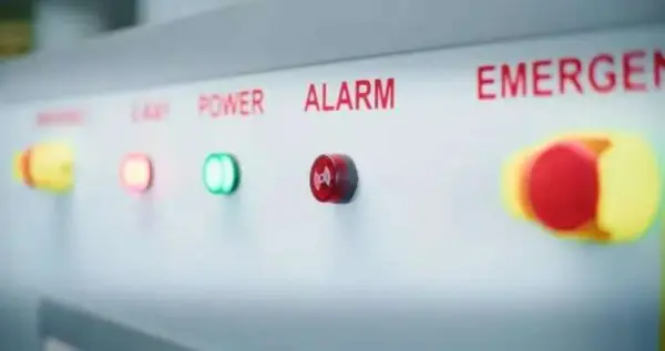
LED Status: For simpler or lower-cost systems, a few well-labeled LEDs can convey basic status: Power, System Running, Warning, Alarm. Combine these with the fault codes stored in memory (accessible maybe via a serial port) for troubleshooting.
Communication and Integration
In industrial-scale implementations, robust networking capabilities become imperative to facilitate centralized supervision and system management.
Optional Communication Features:
The system can be equipped with communication interfaces like UART or I2C. These interfaces allow the system to send temperature data and status updates to a higher-level controller, such as a PC or PLC. This feature enables remote monitoring and makes it easier to integrate the cooling system into larger industrial setups.
Through these communication interfaces, the user can track the system's performance from a central location, receive updates, and even adjust parameters remotely, increasing overall efficiency.
System Integration:
The ability to integrate with other systems makes the intelligent cooling system more versatile. For example, the system could be connected to a central building management system, where it could share information about its operation with other critical systems in the plant.
Such system interoperability enables enhanced operational synchronization, comprehensive data acquisition, and analytical processing, ultimately supporting data-driven operational strategies.
Adding sophisticated diagnostics, clear HMI, and communication options isn't just about extra features; it's about building operational confidence and resilience.
Proactive fault detection prevents catastrophic failures. Intuitive interfaces empower operators with clear status and easy adjustments. Communication capabilities enable remote oversight, valuable data collection, and seamless integration into larger automation systems.
These enhancements transform our PIC-based smart cooling system from a basic controller into a truly professional, reliable, and future-proof solution that operators can trust to protect valuable industrial equipment day in and day out.
Conclusion
In summary, our PIC microcontroller-based smart cooling system effectively transforms a basic, reactive process into a proactive and finely tuned management solution.
By integrating sensing, decision-making, and execution, it delivers clear and practical value: it boosts reliability by preventing overheating and extending component life, enhances safety through multi-layer protection, improves energy efficiency by cooling on-demand, and lowers maintenance costs by enabling predictive alerts.
Looking ahead, this foundation sets the stage for even smarter features. Future upgrades could incorporate more complex algorithms, like fuzzy logic, or add IoT connectivity for cloud-based management and adaptive control.
The versatile and cost-effective PIC platform remains an excellent choice to support these future innovations, ensuring the system stays intelligent and economical.
- What is the core component used as the control brain?
The PIC microcontroller (PIC16F or PIC18F family) serves as the central control brain. - How does the system sense temperature?
Temperature is sensed using NTC thermistors or digital temperature sensors positioned at key points and read via ADC or digital inputs. - Can the PIC directly drive fans and pumps?
No, the PIC uses MOSFETs or relays as driver intermediaries because its I/O cannot handle high power directly. - What control strategies are described for regulating cooling?
The article describes basic threshold control, advanced PID control, and a combined tiered control approach. - How does the system handle catastrophic over-temperature conditions?
A high-priority hardware interrupt, often with a Watchdog Timer, overrides the main loop and forces a safe shutdown on critical faults. - Does the system support user interaction and configuration?
Yes, it supports HMI such as tactile buttons or a rotary encoder for inputs and an LCD or LEDs for status and fault display. - Can the system detect sensor failures or cooling malfunctions?
Yes, it includes sensor fault detection (open/short) and cooling failure prediction by tracking temperature change rates, with multi-level alarms. - Is remote monitoring or integration possible?
Optional communication interfaces like UART or I2C enable remote monitoring and integration with higher-level controllers or building systems. - What advantages does using a PIC microcontroller provide?
PICs offer cost-effectiveness, built-in ADC and PWM, ample I/O, timers, and reliability, reducing external components and complexity.
Related projects
Integrating Solar Power: Microcontroller-Based Approaches for Domestic Electricity
Abstract: Microcontrollers have found extensive application in endeavors aimed at reducing power consumption. The availability of microcontroller development tools has made them...
Power & BatteryEfficient Power Generation with Microcontroller-Controlled Thermoelectric Generators
INTRODUCTION The global demand for electrical energy continues to rise steadily, necessitating a shift towards renewable energy sources as traditional fossil fuels...
Power & BatteryOptimizing Performance: A Guide to Stacking Precision Power Supplies
1. Introduction Statement of Purpose Our project selection stems from the recognition that power supplies represent a crucial and costly aspect of...
Power & Battery10 Mistakes with Hiring a Home Solar Installer and How to Avoid Them
Are you thinking about installing a home solar system? If so, then you're on the right track. Hitting the pavement for the...
Power & Battery · PIC18F252BATTERY CHARACTERIZER using PIC18F252
Introduction This circuit is a battery characterizer that applies a fixed load to a charged NiCad or NiMH cell and measures milliamp-hour...
Power & Battery · PIC12F675PIC 12F675 Programmable 12V Battery Monitor
Being an active outdoor guy, I have a few different types of 12V lights and a variety of battery types. - For...

Ibrar Ayyub
I am an experienced technical writer holding a Master's degree in computer science from BZU Multan, Pakistan University. With a background spanning various industries, particularly in home automation and engineering, I have honed my skills in crafting clear and concise content. Proficient in leveraging infographics and diagrams, I strive to simplify complex concepts for readers. My strength lies in thorough...