Summary of Programming SMD Microcontrollers Without Soldering
Summary: The author attempted to program ATmega328P SMD chips without soldering by pressing the chip onto PCB pads using a SIM/SD-slot style clamp. They designed a PCB with pads, crystal, headers, and USB power, ordered boards from JLCPCB, soldered one chip to verify the circuit, then tried a non-soldered approach but failed and documents the concept and testing. The goal is to program and sell preloaded SMD microcontrollers without permanent soldering.
Parts used in the Wireless Programming Project:
- ATmega328P SMD microcontroller
- PCB with copper pads for SMD chip
- Crystal oscillator
- Power LED
- Pin headers for programming
- USB connector for power
- SD card / SIM card slot or similar push-lock socket
- JLCPCB manufactured prototype boards (5 pcs)
I failed in this wirelessly programming method, But I want to try more methods because finally, we are engineers.
Story
I tried to put my effort to program a single smd Arduino chip without soldering. But I get failed, and now I am here to explain the concept I am thinking. But let’s first discuss the problem and something about Arduino smd chip. And I think it is right title “Wireless Programming” there is no any wires direct wires included in programming.
Arduino smd chip:
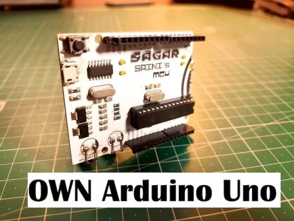
The main microcontroller behind this is ATMEGA328P (8-Bit MCU). By the way, I also made some clones boards – you can see them from here.
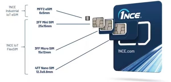
So Atmega328p is available in mostly two packages (DIP and SMD). DIP version is too much big and heavy for the projects like – flight controllers and drones. I am focusing on SMD version of this chip.
Problem:
Basically, I want to program the IC without soldering. Because once the program got loaded in the Ic I can sell the programmed ICs. The new without soldered and bootloader burnt one. The bootloader creates a lot of problems in those clone Arduino boards. Yet, I have the solution for bootloader but I want to program without soldering. And I am trying this with the help of JLCPCB, offering 5 pcs top quality PCB in just $2.
Parameters:
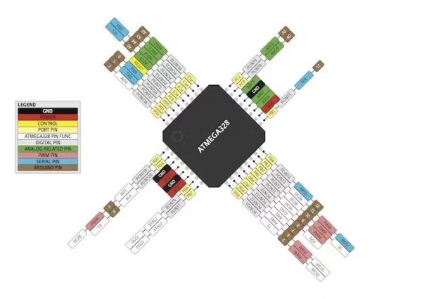
Nowadays this microcontroller is made by Microchip and the package includes these parameters as mentioned in datasheet.
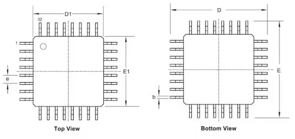
The chip has 32 pins and the total thickness(diameter) of chip is around 1.05mm (without including pins). The thickness of pin metal is 0.15mm and which make the total of 1.20mm.
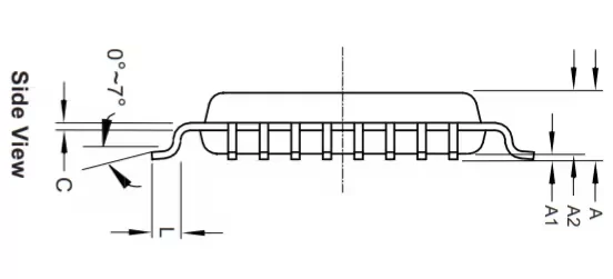
So, this is cleared from the datasheet that pins are mounted beneath of the chip, not in middle and not on the top.
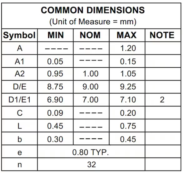
There is around 0.80mm clearance between each pin of the ic and Diameter of each pin is 0.40(normally). All the other parameters are mentioned, so that you can make an idea.
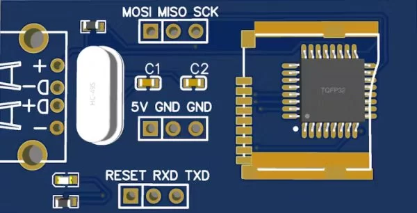
Testing Circuit:
My idea:
I am thinking that, why not to program this chip over the PCB pad. Because there is around 0.15mm between the pins and bottom surface. So, we can press the chip on pcb copper pad, which will make the electrical contracts between the pin and surface. Then we can program it simply.
Then I think about Sd cards and sim slots and that blew my mind. The length* width is (15*11 respectively) and thickness is around 1mm. But there is push lock/unlock option is available. Also, the SIM card technology is using the quite similar tech behind locking system.
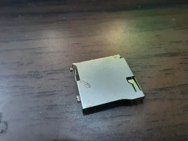
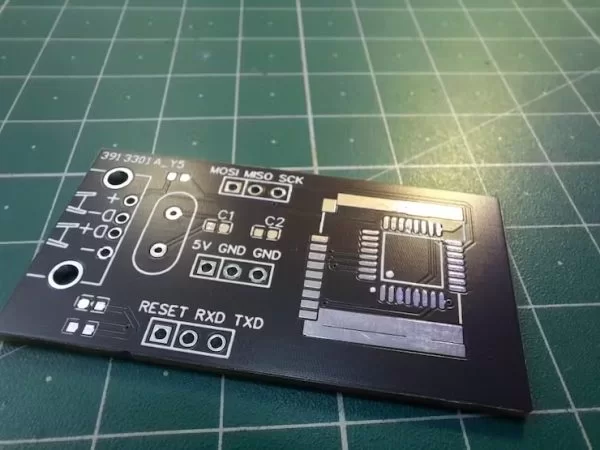
So, I broke my old mobile and MP3 in the search of some golden science behind this. Finally, I decide to make a PCB layout with SD card slot.
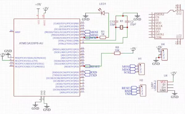
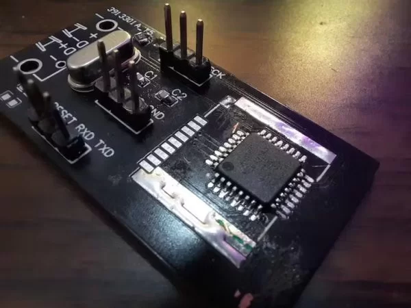
we can Insert the chip inside and adjust the connection between the copper pads. Here is my pcb layout for this. The crystal oscillator is to give proper clock while programming. I use Pin headers for programming and Usb to give power to the circuit.
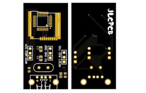
Ordering process:
My link is here for you, Get big discount coupons on your Very first order. Sign-up Now on JLCPCB. And try services like- prototype PCB, Stencils, SMT assembly and 3D-Printing.
Working On idea:
First, I mount all the components on PCB and tried one of these 5 board with soldering the chip on them. And this is working well and now it’s time to program without soldering.
- What microcontroller is used in this wireless programming project?
The project uses the ATmega328P 8-bit AVR microcontroller in SMD package. - Can the ATmega328P SMD chip be programmed without soldering according to the article?
The author attempted to program without soldering by pressing the chip onto PCB pads but reports failure for the wireless programming method. - What is the proposed method to make electrical contact without soldering?
The proposal is to press the SMD chip onto PCB copper pads using a SIM/SD-style push-lock socket so the pins touch the pads. - Why is a crystal oscillator included in the PCB design?
The crystal oscillator is included to provide a proper clock signal while programming. - What role does the power LED play on the PCB?
The power LED indicates board power and will stop glowing if a short circuit occurs. - What precaution does the author mention about connecting the programmer to a laptop?
The author warns of risk to the laptop USB hub and advises trying at your own responsibility. - What manufacturing service did the author use for prototype boards?
The author used JLCPCB to order five prototype PCB boards. - Are the SMD chip pins located on the bottom of the package?
Yes, the article notes the pins are mounted beneath the chip package.