Summary of Mastering the Art of Proportional-Derivative Control with Pulse-Width Modulation
This project details the construction of a hovercraft capable of maintaining orientation and avoiding obstacles. It involves regulating DC motor velocity via an H-bridge circuit, implementing PD control algorithms for stability, and developing high-level logic for obstacle detection using IR sensors. The system utilizes an Atmel microcontroller to manage three fans (one central for lift, two lateral for steering) and integrates LED indicators for status feedback.
Parts used in the Hovercraft Project:
- Atmel Microcontroller
- Current Amplifier Board with H-Bridge circuits
- Central Fan
- Left Fan
- Right Fan
- Battery Power Source
- Infrared (IR) Distance Sensors
- Compass Sensor
- LED Indicators
- Frisbee Base
- Wiring and Connectors
Project Goals
Upon completion of this project, you will have gained the ability to:
1. Regulate the velocity and direction of DC motors using an H-bridge circuit.
2. Execute and fine-tune a proportional-derivative control algorithm to sustain the desired orientation of the hovercraft.
3. Implement an upper-level control algorithm that determines the appropriate instances for braking and the utilization of the PD control approach.
Project Components
All components are required to receive full credit for the project.
Part 1: Microcontroller Circuit
The current amplifier board consists of two complete H-Bridge circuits. We will utilize one full H-Bridge to manage the central fan, giving us control over both its rotation speed and direction. The other H-Bridge will be divided into two “Half Bridges” – one for each of the left and right fans. This division allows us to regulate the speed of these two fans, although direction control is not supported.
For detailed information about the motor control board, please refer to the Lab Hardware page, specifically the section dedicated to the Motor Control Board. A high-level overview of the connections is provided below.
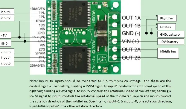
You should establish connections by adding wires to link the motor control board to the fans and the power source:
1. Directly connect the GND and VIN to the battery, avoiding the use of your 5V regulated power supply.
2. Connect the middle fan to port 2 (OUT 2A and 2B).
3. For the right fan, connect the red wire to OUT 1A and the black wire to GND.
4. For the left fan, connect the red wire to OUT 1B and the black wire to GND.
Next, establish connections between the current amplifier board and your Atmel chip (the 15-pin connector located on the left side of the board in the image below):
1. Connect 1PWM and +5V(IN) to your Atmel’s +5V power source.
2. Connect GND and GND to your Atmel’s ground.
3. Select one of the timers (timer1, 3, 4, or 5), ensuring that all three PWM pins (labeled OCXA, OCXB, and OCXC on the Arduino circuit, where X = 1, 3, 4, or 5) are available.
Finally, establish the following connections to your Atmel (avoid using B0 to B3):
1INA: Connect to the Pulse-Width Modulated (PWM) input for the right fan, and link it to OCXA.
1INB: Link to the PWM input for the left fan, and connect it to OCXB.
2PWM: Connect to the PWM input for the middle fan, and attach it to OCXC.
2INB/2INA: These pins control the direction of the middle fan (0/1 for one direction, 1/0 for the other). Connect them to available digital output pins.
Part 2: Fan Control Interface
Please be aware that this section contributes towards a single personal programming credit.
Create the function interface responsible for generating PWM signals for each of the three PWM inputs to the motor control board.
In “project.h,” define two new variable types as follows:
1. MotorDirection (an enumeration type) with two values: BRAKE and HOVER.
2. SensorSide (an enumeration type) with two values: LEFT and RIGHT.
Ensure to include “project.h” in your C file.
Implement the following functions:
1. set_middle_direction(MotorDirection direction):
– This function sets the direction bits for the middle fan.
– When direction is HOVER, it implies that the craft should hover (provided an appropriate thrust level).
– When direction is BRAKE, it implies that the craft should descend to the ground.
2. set_middle_magnitude(int16_t magnitude):
– This function adjusts the thrust magnitude for the middle fan.
– Ensure that the magnitude falls within the range of 0 to 1023, which corresponds to a duty cycle range of 0% to 100%. If the value exceeds this range, clip it accordingly.
3. set_lateral_magnitudes(int16_t magnitude_left, int16_t magnitude_right):
– This function configures the thrust magnitude for the left and right fans.
– Ensure that both magnitude_left and magnitude_right fall within the range of 0 to 1023 (0% to 100% duty cycle). If either value exceeds this range, limit it accordingly.
Please note:
The initialization of the three PWM channels should take place within your main() function. Refer to the lecture notes on timers for guidance.
Testing
Implement the following test functions:
1. testing_case_1():
– Set thrust direction to HOVER.
– Note the initial heading (referred to as your “goal”).
– Gradually increase the thrust of the middle fan until the heading error exceeds 45 degrees.
– Gradually decrease the thrust of the middle fan until it reaches zero.
– Set the thrust direction to BRAKE.
– Use your LEDs to indicate the current phase of the program.
2. testing_case_2():
– Gradually increase the duty cycle of the left fan to 25%.
– While decreasing the duty cycle of the left fan to 0%, gradually increase the duty cycle of the right fan to 25%.
– Gradually decrease the duty cycle of the right fan to 0%.
– Use your LEDs to indicate the current phase of the program.
Modify your main function to execute one of the two functions mentioned above, depending on the initial state of switch 0.
Part 3: Proportional Derivative Control
Please be advised that this section contributes to a single personal programming credit.
Create a function responsible for implementing a proportional-derivative controller:
void pd_control(int16_t error, int16_t rotation_rate, uint16_t forward_thrust);
Here’s what the function parameters represent:
– “error” denotes the heading error.
– “rotation_rate” is the rate of the craft’s rotation.
– “forward_thrust” stands for the total forward thrust, which is the sum of the left and right thrust magnitudes (this value will fall within the range of 0 to 1023).
The function should carry out the following tasks:
1. Compute a left/right differential control signal for the fans by applying the proportional-derivative control law. This control law should incorporate both the heading error and the current rotation rate. Within this function, ensure that the heading error considers a small dead-band around zero error and maximum error values (a good starting point is: a dead-band of +/- 5 degrees and a max error of +/- 45 degrees).
2. Add the calculated differential control signal to the “forward_thrust” input.
3. Set “magnitude_left” and “magnitude_right.”
Note: Be mindful that integer mathematics is more efficient; however, you must exercise caution regarding data types and the sequence of multiplication and division operations.
Additional insights on tuning the PD control parameters:
– Begin with Kp (Proportional Gain) set to 0 and gradually increase Kv (Derivative Gain) to an appropriate level. Your craft should exhibit resistance to rotation. If it accelerates instead, it’s likely that the sign of Kv is incorrect.
– Subsequently, set Kv to 0 and increment Kp gradually to a suitable level. Expect to observe oscillations, and that’s acceptable for now. If the craft turns away from the desired heading, it indicates the sign of Kp may be incorrect.
– With your chosen Kp and Kv, when oscillations occur, your choices are to increase Kv or decrease Kp. Make these adjustments gradually.
– It’s possible for Kp to be excessively high, which stems from the inherent delay between control decisions. A larger delay leads to more significant oscillations. In this scenario, your only recourse is to reduce Kp (and likely Kv as well).
Part 4: High-Level Control
Please take note that this segment also contributes to a single personal programming credit.
In this part, you will implement a high-level control loop that cycles every 50 milliseconds. During each of these control steps, if no obstacles are in sight, the craft will hover and move forward. If an obstacle is detected, the craft should engage the brakes.
Modify your program structure to adhere to the following outline (naturally, you will need to incorporate additional code as required):
[Insert structure of your program here]// Global flag
volatile uint8_t flag_timing = 0;
// Interrupt service routine: called every time
// the timer 0 counter transitions from 0xFF to 0.
// Period of flag_timing is 3 * 256 * 1024 / 16000000 = 49.152 ms
ISR(TIMER0_OVF_vect) {
static uint8_t count = 0; // Set to zero at beginning of program only
if(++count == 3){
// Set the flag to indicate that the period has passed
flag_timing = 1;
count = 0;
}
};
int main(void) {
int16_t counter = 0;
int16_t heading, heading_last, heading_goal, heading_error;
int16_t rotation_rate, distance_left, distance_right;
#APPROPRIATE VARIABLE DECLARATIONS HERE#
#APPROPRIATE INITIALIZATIONS HERE#
timer0_config(TIMER0_PRE_1024); // Prescale by 1024
timer0_enable(); // Enable the timer 0 overflow interrupt
sei(); // Enable global interrupts
// Initialize variables
heading_goal = get_heading();
distance_left = get_ir_distance(LEFT);
distance_right = get_ir_distance(RIGHT);
// Begin to lift off the ground
set_middle_direction(HOVER);
#RAMP UP MIDDLE THRUST TO HOVER#
// Loop for ~30 seconds
while(counter < 20*30) {
heading = get_heading();
heading_error = compute_heading_error(heading, heading_goal);
rotation_rate = get_rotation_rate();
distance_left = get_ir_distance(LEFT);
distance_right = get_ir_distance(RIGHT);
// Display
#APPROPRIATE CODE FOR DISPLAYING SENSOR STATES WITH YOUR LEDS#
// Obstacles?
if(#obstacles#) {
#BRAKE#
}else{
// No obstacles: steer to desired heading
pd_control(heading_error, rotation_rate, #PICK AN APPROPRIATE VALUE#);
}
// Increment time
++counter;
if(flag_timing) {
// Error condition: your code body is taking too much
// time.
#Indicate this with an LED display of some form#
}
// Wait for the flag to be set (happens once every ~50 ms)
while(flag_timing == 0) {};
// Clear the flag for next time.
flag_timing = 0;
}
#RAMP DOWN MIDDLE THRUST TO ZERO#
while(1){}; // Spin forever
}
Part 5: Hovercraft Layout
Take another look at how you’ve attached your components to the Frisbees:
1. Ensure that all components and cables are firmly fastened and that no wires come close to the fans.
2. Confirm that the compass is situated at a considerable distance from the motors and any wires carrying significant electrical currents.
3. Verify that the Frisbee is properly balanced, meaning that the center of mass aligns with the center of the Frisbee.
If you require any additional components or assistance with the mounting process, please inform us.
Source: Mastering the Art of Proportional-Derivative Control with Pulse-Width Modulation
-
How should the battery be connected to the current amplifier board?
Directly connect the GND and VIN to the battery, avoiding the use of the 5V regulated power supply. -
Can direction control be applied to the left and right fans?
No, direction control is not supported for the left and right fans; only speed regulation is possible for these units. -
What is the purpose of the MotorDirection enumeration values BRAKE and HOVER?
HOVER implies the craft should maintain altitude, while BRAKE implies the craft should descend to the ground. -
What range must the thrust magnitude values fall within for the fan functions?
The magnitude values must fall within the range of 0 to 1023, corresponding to a duty cycle of 0% to 100%. -
How does the Proportional Derivative controller handle heading errors near zero?
The function considers a small dead-band around zero error, with a suggested starting point of +/- 5 degrees. -
What is the recommended sequence for tuning Kp and Kv gains?
Begin with Kp set to 0 and gradually increase Kv, then set Kv to 0 and increment Kp gradually. -
How often does the high-level control loop execute?
The high-level control loop cycles every 50 milliseconds. -
What action does the craft take if an obstacle is detected?
If an obstacle is detected, the craft engages the brakes.